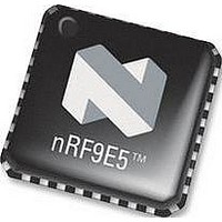
NRF9E5 NORDIC SEMICONDUCTOR, NRF9E5 Datasheet - Page 76

NRF9E5
Manufacturer Part Number
NRF9E5
Description
TRX, 430-928MHZ, MCU/ADC/PWM, SMD
Manufacturer
NORDIC SEMICONDUCTOR
Datasheet
1.NRF9E5.pdf
(108 pages)
Specifications of NRF9E5
Receiving Current
12.5mA
Transmitting Current
30mA
Data Rate
50Kbps
Frequency Range
430MHz To 928MHz
Modulation Type
GFSK
Rf Ic Case Style
QFN
No. Of Pins
32
Supply Voltage Range
1.9V To
Lead Free Status / RoHS Status
Lead free / RoHS Compliant
Available stocks
Company
Part Number
Manufacturer
Quantity
Price
Company:
Part Number:
NRF9E5C
Manufacturer:
NORDIC
Quantity:
5 000
Part Number:
NRF9E5C
Manufacturer:
NORDIC
Quantity:
20 000
PRODUCT SPECIFICATION
nRF9E5 Single Chip Transceiver with Embedded Microcontroller and ADC
18.8 Timers/Counters
The nRF9E5 includes three timer/counters (Timer 0, Timer 1 and Timer 2). Each
timer/counter can operate as either a timer with a clock rate based on the CPU clock , or
as an event counter clocked by the t0 pin (Timer 0), t1 pin (Timer 1), or the T2 pin
(Timer 2). These pins are alternate function bits of Port 0 and 1 as this : t0 is P0.5, t1 is
P0.6 and T2 is P1.0, for details please see ch. 6.3 on page 16.
Each timer/counter consists of a 16-bit register that is accessible to software as three
SFRs: (Table 61)
18.8.1 Timers 0 and 1
Timers 0 and 1 each operate in four modes, as controlled through the TMOD SFR
(Table 65) and the TCON SFR (Table 66). The four modes are:
Bit
TMOD.7
TMOD.6
TMOD.5
TMOD.4
TMOD.3
TMOD.2
TMOD.1
TMOD.0
Main office: Nordic Semiconductor ASA - Vestre Rosten 81, N-7075 Tiller, Norway -Phone +4772898900 - Fax +4772898989
Revision: 1.3
-
-
-
-
13-bit timer/counter (mode 0)
16-bit timer/counter (mode 1)
8-bit counter with auto-reload (mode 2)
Two 8-bit counters (mode 3, Timer 0 only)
Timer 0 - TL0 and TH0
Timer 1 - TL1 and TH1
Timer 2 - TL2 and TH2
Function
GATE - Timer 1 gate control. When GATE = 1, Timer 1 will clock only when external
interrupt INT1_N = 1 and TR1 (TCON.6) = 1. When GATE = 0, Timer 1 will clock only
when TR1 = 1, regardless of the state of INT1_N.
C/T - Counter/Timer select. When C/T = 0, Timer 1 is clocked by CPU_clk/4 or
CPU_clk/12, depending on the state of T1M (CKCON.4). When C/T = 1, Timer 1 is clocked
by the t1 pin.
M1 - Timer 1 mode select bit 1.
M0 - Timer 1 mode select bit 0, decoded as:
GATE - Timer 0 gate control. When GATE = 1, Timer 0 will clock only when external
interrupt INT0_N = 1 and TR0 (TCON.4) = 1. When GATE = 0, Timer 0 will clock only
when TR0 = 1, regardless of the state of INT0_N.
C/T - Counter/Timer select. When C/T = 0, Timer 0 is clocked by CPU_clk/4 or
CPU_clk/12, depending on the state of T0M (CKCON.3). When C/T = 1, Timer 0 is clocked
by the t0 pin.
M1 - Timer 0 mode select bit 1.
M0 - Timer 0 mode select bit 0, decoded as:
M1 M0 Mode
M1 M0 Mode
00 Mode 0 : 13-bit counter
01 Mode 1 : 16-bit counter
10 Mode 2 : 8-bit counter with auto-reload
11 Mode 3 : Two 8-bit counters
00 Mode 0 : 13-bit counter
01 Mode 1 : 16-bit counter
10 Mode 2 : 8-bit counter with auto-reload
11 Mode 3 : Two 8-bit counters
Table 65 TMOD Register – SFR 0x89.
Page 76 of 108
June 2006


