80.91.0.240.0000 FINDER, 80.91.0.240.0000 Datasheet
80.91.0.240.0000
Specifications of 80.91.0.240.0000


Related parts for 80.91.0.240.0000


80.91.0.240.0000 Summary of contents
Page 1
... Relays, Timers, Interface Modules, Sockets and Accessories. 2002 - 2003 Catalogue The power in relays and timers since 1954 ® S.p.A. ISO 9001 ISO 14001 ...
Page 2
...
Page 3
... NEMKO, RINA, SEV, SEMKO, UL, UTE and VDE, and through CE certification important as these quality approvals are, Finder considers it no more important than its partnerships with customers, who are able to value the quality of its products and after-sales service. For up-to-date information regarding Finder, ...
Page 4
... FINDER S.p.A. Via Drubiaglio, 14 10040 ALMESE (TO) ITALIA For further information on the following, please complete and return: Name: ......................................................... Position: ....................................................... Company: ......................................................................................................................... Address: ........................................................................................................................... ...................................................................... Postcode: .................................................... Telephone: ......................................................... Fax: ........................................................ Finder customer: PRICE LIST CATALOG ON CD-ROM SALES ENGINEER TO VISIT YES NO Fax-back form Tel.+39/011.9346211 Fax +39/011.9359079 Export@findernet.com ...
Page 5
... Series.................................Page 24 Low-Profile P.C.B. Relays Series.................................Page 28 Miniature P.C.B. Relays Series.................................Page 34 Miniature P.C.B. + Faston 250 Relays Series.................................Page 37 Miniature General Purpose Relays Series.................................Page 46 Miniature Power Relays Series.................................Page 53 General Purpose Relays Series.................................Page 62 Power Relays Series.................................Page 72 Power Relays ...
Page 6
... Electrical life at rated load AC1 Operate/release time (bounce included) Insulation according to EN 61810-5 Insulation between coil and contacts (1.2/50µs) kV Dielectric strength between open contacts V AC Ambient temperature range Environmental protection Approvals: (according to type Series - Subminiature D.I.L. Relays 1.25 A 30.22 - Low consumption - P.C.B. mounting ...
Page 7
... 7.005 3.7 7.5 6 7.006 4 7.009 6.7 13.5 12 7.012 8 7.024 16 7.048 Series - Subminiature D.I.L. Relays 1. Contact material 0 = Standard AgNi + Au (5µm) B: Contact circuit insulation rated voltage rated impulse withstand voltage pollution degree overvoltage category g/g 10/10 W 0.2 with rated current W 0.4 ≥5 ...
Page 8
... Electrical life at rated load AC1 Operate/release time (bounce included) Insulation according to EN 61810-5 Insulation between coil and contacts (1.2/50µs) kV Dielectric strength between open contacts Ambient temperature range Environmental protection Approvals: (according to type Series - Slim Electromechanical Relays 6 A 34. wide - P.C.B. mounting 0.8 1 ...
Page 9
Ultra-slim wide - High switching speed and endurance - Silent switching 1.3 Output circuit Maximum switching current Rated voltage V DC Switching voltage range V DC Maximum blocking voltage V DC Input ...
Page 10
... Contact material 0 = Standard AgNi 4 = AgSnO AgNi + Au B: Contact circuit Output circuit 9024 = VDC 7048 = 100 VDC without contact current W 0.17 with rated current W 0.4 Release Control voltage current Series - Slim Relays Special versions 0 = Flux proof (RT II) C: Options 1 = None ...
Page 11
... ELECTROMECHANICAL RELAY TECHNICAL DATA INSULATION INSULATION according to EN 61810-5 IMMUNITY CONDUCTED DISTURBANCE IMMUNITY OTHER DATA VIBRATION RESISTANCE (10…55Hz): NO/NC POWER LOST TO THE ENVIRONMENT without contact current RECOMMENDED DISTANCE between RELAYS mounted on P.C.B.s mm CONTACT SPECIFICATIONS LOAD RATED CURRENT (A) Electrical life vs AC1 load. ...
Page 12
... Operate/release time (bounce included) Insulation according to EN 61810-5 Insulation between coil and contacts (1.2/50µs) kV Dielectric strength between open contacts Ambient temperature range Envirommental protection Approvals: (according to type Series - Miniature P.C.B. Relays 10 A 36.11 - Sugar cube - Sugar cube - P.C.B. mounting - P.C.B. mounting 2.2 Ø ...
Page 13
... 9.003 2.2 4.5 5 9.005 3.7 7.5 6 9.006 4 9.009 6.7 13.5 12 9.012 9.024 9.048 Series - Miniature P.C.B. Relays Contact material 0 = Standard AgCdO B: Contact circuit insulation rated voltage rated impulse withstand voltage pollution degree overvoltage category 0.2 0 Breaking capacity in DC1 load. ...
Page 14
... Insulation according to EN 61810-5 Insulation between coil and contacts (1.2/50µs) kV Dielectric strength between open contacts Ambient temperature range Envirommental protection Approvals: (according to type Series - Miniature P.C.B. Relays 40. pole pole 3.5 mm pinning - 5 mm pinning - P.C.B. / for use with 95 series sockets - P.C.B. / for use with 95 series sockets ...
Page 15
... Series - Miniature P.C.B. Relays P.C.B. or plug-in mount - AC, DC, sensitive DC or single bistable coil versions available - 8 mm (1.2/50 µs) between coil and contacts - Ambient temperature +85°C - Sockets and accessories: see 95, 99 and 86 series - RT III (wash tight) version available 29 12.4 0 for 400 V applications, requirements for pollution degree 2 are met ...
Page 16
... DC Coil voltage see coil specifications TECHNICAL DATA INSULATION INSULATION according to EN 61810-5 IMMUNITY CONDUCTED DISTURBANCE IMMUNITY OTHER DATA VIBRATION RESISTANCE (10…55Hz): NO/NC POWER LOST TO THE ENVIRONMENT RECOMMENDED DISTANCE between RELAYS mounted on P.C.B Series - Miniature P.C.B. Relays Contact material 0 = Standard AgNi for: 40.31/51/52 AgCdO for 40 ...
Page 17
... Series - Miniature P.C.B. Relays CONTACT SPECIFICATIONS LOAD RATED CURRENT (A) Electrical life vs AC1 load Type 40. Type 40.31 - 40.51 ( Type 40.61 (16 A) COIL SPECIFICATIONS DC VERSION DATA (0.65 W standard) Nominal Coil Operating range voltage code min max 9.005 3.65 7.5 6 9.006 4 9.007 5.1 10 ...
Page 18
... On momentary closure of the RESET switch the relay is demagnetised through limiting resistor (R ) and the contacts return to the AC reset position. Notes: The minimum SET or RESET impulse time is 20 ms. The maximum time can be continuous. In practice, always ensure that the SET and RESET contacts cannot be operated simultaneously Series - Miniature P.C.B. Relays sens Operating range vs ambient temperature ...
Page 19
... Series - Sockets and Accessories for 40 Series Relays Relay type Colour Clamp terminal socket: panel rail (EN 50022) mount, 95.03 retaining clip 095.01 supplied with socket packaging code SPA 95.05 Plastic retaining and release clip Approvals Metal retaining clip (according to type): 8-way jumper link for 95.03 and 95.05 sockets ...
Page 20
... Series - Sockets and Accessories for 40 Series Relays Relay type Colour Clamp terminal socket: panel rail (EN 50022) mount 95.63 retaining clip 095.71 supplied with socket packaging code SMA 95.63 Metal retaining clip 40 8-way jumper link for 95.63 and 95.75 sockets Modules (see table below) 95.65 Ø ...
Page 21
... Series - Sockets and Accessories for 40 Series Relays Relay type Colour P.C.B. socket retaining clip 095.51 supplied with socket packaging code SMA 95.13 Metal retaining clip Plastic retaing clip 95.15 Approvals (according to type): ® GOST RATED VALUES 250 V - INSULATION: ≥ (1.2/50µs) between coil and contacts - PROTECTION CATEGORY AMBIENT TEMPERATURE: (-40… ...
Page 22
... Series - Low-Profile P.C.B. Relays Low-profile, only 15.7 mm high - DC coil versions 0 mm, 6 kV(1.2/50 µs) between coil and contacts - Ambient temperature +85°C - Sockets and accessories: see 95 and 99 series 41 29 12.7 0.6 0.8 * for 400 V applications, requirements for pollution degree 2 are met. Contact specifications ...
Page 23
... Series - Low-Profile P.C.B. Relays ORDERING INFORMATION Example series low-profile P.C.B. relay with 2 CO contacts, with coil rated Series Type 3 = P.C.B. - 3.5 mm pinning 5 = P.C. pinning 6 = P.C. pinning No. of poles pole for 41.31 41.61 pole for 41.52 Coil version Coil voltage see coil specifications ...
Page 24
... Series - Low-Profile P.C.B. Relays CONTACT SPECIFICATIONS LOAD RATED CURRENT (A) Contact life vs AC1 load Type 41. 360 cycles/ Type 41.31 ( 360 cycles/ Type 41.61 ( 360 cycles/h. COIL SPECIFICATIONS DC VERSION DATA Nominal Coil Operating range voltage code min 9.012 8.4 24 9.024 16.8 48 9.048 33 ...
Page 25
... Series - Sockets and Accessories for 41 Series Relays Relay type Colour P.C.B. socket retaining clip 095.41 supplied with socket packaging code SNA 95.13 Metal retaining clip Plastic retaining clip 95.15 Approvals (according to type): ® GOST RATED VALUES 250 V - INSULATION: ≥ (1.2/50µs) between coil and contacts - PROTECTION CATEGORY AMBIENT TEMPERATURE: (-40… ...
Page 26
... Operate/release time (bounce included) Insulation according to EN 61810-5 Insulation between coil and contacts (1.2/50µs) kV Dielectric strength between open contacts Ambient temperature range Environmental protection Approvals: (according to type Series - Low Profile P.C.B. Relays 10 A 43. 3.2 mm pinning - 5 mm pinning - P.C.B. mounting or sockets 95 series - P.C.B. mounting ...
Page 27
... Sensitive DC Coil voltage see coil specifications TECHNICAL DATA INSULATION INSULATION according to EN 61810-5 OTHER DATA VIBRATION RESISTANCE (10…55Hz): NO/NC POWER LOST TO THE ENVIRONMENT without contact current RECOMMENDED DISTANCE between RELAYS mounted on P.C.B Series - Low Profile P.C.B. Relays Contact material 2 = Standard AgCdO ...
Page 28
... Series - Low Profile P.C.B. Relays Breaking capacity in DC1 load. • When switching a resistive load (DC1) having voltage and current values under the curve the expected electrical life is ≥ 100·10 • In case of DC13 loads the connection of a diode in parallel with the load will permit the same electrical life as for a DC1 load ...
Page 29
... Series - Sockets and Accessories for 43 Series Relays Relay type Colour P.C.B. socket (only for CO version) retaining clip 095.43 supplied with socket packaging code SNA 95.23 Metal retainig clip Approvals (according to type): ® GOST RATED VALUES 250 V - INSULATION: ≥ (1.2/50µs) between coil and contacts - PROTECTION CATEGORY AMBIENT TEMPERATURE: (-40… ...
Page 30
... Insulation according to EN 61810-5 Insulation between coil and contacts (1.2/50µs) kV Dielectric strength between open contacts Ambient temperature range Environmental protection Approvals: (according to type Series - Miniature P.C.B. Relays 44. pole pole pinning - 5 mm pinning - P.C.B./ for use with 95 series sockets - P.C.B./ for use with 95 series sockets ...
Page 31
... TECHNICAL DATA INSULATION INSULATION according to EN 61810-5 IMMUNITY CONDUCTED DISTURBANCE IMMUNITY OTHER DATA VIBRATION RESISTANCE (10…55Hz): NO/NC POWER LOST TO THE ENVIRONMENT without contact current RECOMMENDED DISTANCE between RELAYS mounted on P.C.B Series - Miniature P.C.B. Relays Contact material 0 = Standard AgNi ...
Page 32
... AMBIENT TEMPERATURE (°C) Operating range (DC version) vs ambient temperature Max coil voltage permitted Min pick-up voltage with coil at ambient temperature Series - Miniature P.C.B. Relays Breaking capacity for DC1 load Type 44. Type 44. Load applied to 1 contact B - Load applied to 2 contacts in series • When switching a resistive load (DC1) having voltage and current values under the curve the expected electrical life is ≥ ...
Page 33
... Series - Sockets and Accessories for 44 Series Relays Relay type Colour Clamp terminal socket: panel rail (EN 50022) mount retaining clip 095.01 supplied with socket packaging code SPA 95.05 Retaining and release clip Approvals Metal retaining clip (according to type): 8-way jumper link for 95.03 and 95.05 sockets ...
Page 34
... Series - Sockets and Accessories for 44 Series Relays Relay type Colour Clamp terminal socket: panel rail (EN 50022) mount retaining clip 095.71 supplied with socket packaging code SMA 95.65 Metal retaining clip 8-way jumper link for 95.65 and 95.75 sockets Modules (see table below) 95 ...
Page 35
... Series - Sockets and Accessories for 44 Series Relays Relay type Colour P.C.B. socket retaining clip 095.51 supplied with socket with packagimg code SMA 95.15 Retaining clip Approvals Plastic retaining clip (according to type): ® GOST RATED VALUES 250 V - INSULATION: ≥ (1.2/50µs) between coil and contacts - PROTECTION CATEGORY AMBIENT TEMPERATURE: (-40… ...
Page 36
... Operate/release time (bounce included) Insulation according to EN 61810-5 Insulation between coil and contacts (1.2/50µs) kV Dielectric strength between open contacts Ambient temperature range Environmental protection Approvals: (according to type Series - Miniature P.C.B. Relays 16 A 45. Max ambient temperature +125°C - P.C.B. mounting + Faston 250 ...
Page 37
... VIBRATION RESISTANCE (10…55Hz): NO/NC POWER LOST TO THE ENVIRONMENT without contact current RECOMMENDED DISTANCE between RELAYS mounted on P.C.B.s mm CONTACT SPECIFICATIONS LOAD RATED CURRENT (A) Electrical life AC1 load (+85°C). 45 Series - Miniature P.C.B. Relays Contact material 0 = Standard AgCdO B: Contact circuit insulation rated voltage rated impulse withstand voltage ...
Page 38
... DC VERSION DATA (0.36 W sensitive) Nominal Coil Operating range voltage code min 7.006 4.2 12 7.012 8.4 24 7.024 16.8 48 7.048 33.6 60 7.060 Series - Miniature P.C.B. Relays Resistance Rated coil U consumption max Ω 7.2 100 60 14.4 400 30 28.8 1,600 15 57.6 6,400 7.5 72 10,000 6 Operating range vs ambient temperature. ...
Page 39
... Series - Miniature General Purpose Relays 5 - Plug-in or P.C.B. versions - coils - Lockable test button and mechanical flag indicator as standard on 2 and 4 CO relays types - Sockets and accessories: see 94, 99 and 86 series - RT III (wash tight) version available Contact specifications Contact configuration Rated current/Maximum peak current ...
Page 40
... Series - Miniature General Purpose Relays 5 - Plug-in or P.C.B. versions - coils - Lockable test button and mechanical flag indicator as standard on 2 and 4 CO relays types - Sockets and accessories: see 94, 99 and 86 series 55 Contact specifications Contact configuration Rated current/Maximum peak current Rated voltage/Maximum switching voltage V AC ...
Page 41
... LOCKABLE TEST BUTTON AND MECHANICAL FLAG INDICATOR (0040) The dual-purpose Finder test button can be used in two ways: Case 1) The plastic pip (located directly above the test button) remains intact. In this case, when the test button is pushed, the contacts operate. When the test button is released the contacts return to their former state ...
Page 42
... Series - Miniature General Purpose Relays 5 -10 A TECHNICAL DATA INSULATION INSULATION according to EN 61810-5 IMMUNITY CONDUCTED DISTURBANCE IMMUNITY OTHER DATA VIBRATION RESISTANCE (10…55Hz): NO/NC POWER LOST TO THE ENVIRONMENT 55 RECOMMENDED DISTANCE between RELAYS mounted on P.C.B.s CONTACT SPECIFICATIONS LOAD RATED CURRENT (A) Electrical life vs AC1 load. ...
Page 43
... Series - Miniature General Purpose Relays 5 -10 A COIL SPECIFICATIONS AC VERSION DATA Nominal Coil Operating range voltage code min max 8.006 4.8 6.6 12 8.012 9.6 13.2 24 8.024 19.2 26.4 48 8.048 38.4 52.8 60 8.060 48 66 110 8.110 88 121 120 8.120 96 132 230 8.230 184 ...
Page 44
... Series - Sockets and Accessories for 55 Series Relays Relay type Colour Clamp terminal socket: panel rail (EN 50022) mount retaining clip 094.71 supplied with socket packaging code SMA 94.04 Metal retaining clip Approvals Plastic retaining and release clip (according to type): 6-way jumper link for 94.02, 94.03 and 94.04 sockets ...
Page 45
... Series - Sockets and Accessories for 55 Series Relays Relay type Colour Screw terminal socket: panel rail (EN 50022) mount retaining clip 094.71 supplied with socket packaging code SMA 94.74 Retaining clip Approvals Modules (see table below) (according to type): ® GOST RATED VALUES 250 V - DIELECTRIC STRENGTH: ≥ ...
Page 46
... Series - Sockets and Accessories for 55 Series Relays Relay type Colour Clamp terminal socket: panel rail (EN 50022) mount retaining clip 094.71 supplied with socket packaging code SMA 94.84.1 Retaining clip Approvals Plastic retaining and release clip (according to type): Identification tag Modules (see table below) ...
Page 47
... Series - Sockets and Accessories for 55 Series Relays Relay type Colour Panel mount solder socket thick panel retaining clip 094.51 supplied with socket packaging code SMA 94.22 Metal retaining clip Approvals (according to type): ® GOST RATED VALUES 250 V - DIELECTRIC STRENGTH: ≥ AMBIENT TEMPERATURE: (-40…+70)°C ...
Page 48
... Insulation between coil and contacts (1.2/50µs) kV Dielectric strength between open contacts Ambient temperature range Environmental protection Approvals: (according to type Series - Miniature Power Relays 12 A 56. pole - 2 NO (1.5 mm gap) - Plug-in for use with 96 Series - Plug-in for use with 96 Series sockets (Faston 187 - 4.8x0.5mm) sockets (Faston 187 - 4 ...
Page 49
... Insulation according to EN 61810-5 Insulation between coil and contacts (1.2/50µs) kV Dielectric strength between open contacts V AC Ambient temperature range Environmental protection Approvals: (according to type) 56 Series - Miniature Power Relays 12 A 56.42 56.42 - 0300 - 2 pole - 2 NO (1.5 mm gap) - P.C.B. mounting - P.C.B. mounting ...
Page 50
... REAR FLANGE MOUNT LOCKABLE TEST BUTTON AND MECHANICAL FLAG INDICATOR (0040) The dual-purpose Finder test button can be used in two ways: Case 1) The plastic pip (located directly above the test button) remains intact. In this case, when the test button is pushed, the contacts operate. When the test button is released the contacts return to their former state ...
Page 51
... In case of DC13 loads the connection of a diode in parallel with the load will permit the same electrical life as for a DC1 load. Note: the release time of load will be increase. 56 Series - Miniature Power Relays 12 A insulation rated voltage rated impulse withstand voltage pollution degree ...
Page 52
... AMBIENT TEMPERATURE (° CO 1.5 1.0 0.5 - AMBIENT TEMPERATURE (°C) Operating range (AC type) vs ambient temperature Max coil voltage permitted Min pick-up voltage with coil at ambient temperature Series - Miniature Power Relays VERSION DATA (2 CO) Resistance Rated coil Nominal consumption voltage (50Hz) U max Ω 6.6 ...
Page 53
... Series - Sockets and Accessories for 56 Series Relays Relay type Colour Screw terminal socket: panel rail (EN 50022) mount retaining clip 094.71/096.71 supplied with socket packaging code SMA 96.72 Retaining clip Modules (see table below) 96.74 Approvals (according to type): ® GOST RATED VALUES 250 V - DIELECTRIC STRENGTH: ≥ ...
Page 54
... Series - Sockets and Accessories for 56 Series Relays Relay type Colour P.C.B. socket retaining clip 094.51 supplied with socket packaging code SMA 96.12 Retaining clip Approvals (according to type): ® RATED VALUES 250 V (10 A max for each contact circuit) - DIELECTRIC STRENGTH: ≥ AMBIENT TEMPERATURE: (-40…+70)°C ...
Page 55
... Insulation according to EN 61810-5 Insulation between coil and contacts (1.2/50µs) kV Dielectric strength between open contacts V AC Ambient temperature range Environmental protection Approvals: (according to type) 60 Series - General Purpose Relays 10 A 60.12 60.12 - 0200 - 2 pole - 2 bifurcated contacts - 8 pin - 8 pin - Plug-In for use with 90 series sockets ...
Page 56
... Insulation according to EN 61810-5 Insulation between coil and contacts (1.2/50µs) kV Dielectric strength between open contacts Ambient temperature range Environmental protection Approvals: (according to type Series - General Purpose Relays 10 A 60.13 - 0200 - 3 bifurcated contacts - 2 pole - 11 pin - Faston 187 (4.8x0.8)mm - Plug-In for use with 90 series sockets ...
Page 57
... Sheet of marker tags see page 60. LOCKABLE TEST BUTTON AND MECHANICAL FLAG INDICATOR (0040) The dual-purpose Finder test button can be used in two ways: Case 1) The plastic pip (located directly above the test button) remains intact. In this case, when the test button is pushed, the contacts operate. When the test button is released the contacts return to their former state ...
Page 58
... LOAD RATED CURRENT (A) Electrical life vs AC1 load Series - General Purpose Relays 10 A insulation rated voltage rated impulse withstand voltage pollution degree overvoltage category BURST (according to EN 61000-4-4) level 4 (4kV) SURGE (according to EN 61000-4-5) level 4 (4kV) g/g 5 without contact current W 1.3 with rated current W 2 ...
Page 59
... Series - CURRENT SENSING DC Coil code 4202 4182 4162 4142 4122 4102 4092 4062 4032 4012 Other types of current sensing relays are available on request. Operating range Resistance Rated coil consumption min max 4.8 6.6 28 214 9.6 13.2 ...
Page 60
... Series - Sockets and Accessories for 60 Series Relays Relay type Colour Clamp terminal socket: panel rail (EN 50022) mount retaining clip 090.33 supplied with socket packaging code SMA 90.21 Retaining clip Approvals Modules (see table below) (according to type): ® GOST RATED VALUES 250 V ...
Page 61
... Series - Sockets and Accessories for 60 Series Relays Relay type Colour Clamp terminal socket: panel rail (EN 50022) mount Retaining clip 90.73 Timer module Approvals (according to type): GOST - Double ground terminal (A2). - RATED VALUES 250 V - DIELECTRIC STRENGTH PROTECTION CATEGORY AMBIENT TEMPERATURE: (-40…+70)°C - SCREW TORQUE: 0.8 Nm ...
Page 62
... Series - Sockets and Accessories for 60 Series Relays Relay type Colour Screw terminal socket: panel rail (EN 50022) mount retaining clip 090.33 supplied with socket packaging code SMA 90.26 Retaining clip Approvals (according to type): ® GOST RATED VALUES 250 V - DIELECTRIC STRENGTH PROTECTION CATEGORY AMBIENT TEMPERATURE: (-40… ...
Page 63
... Series - Sockets and Accessories for 60 Series Relays PACKAGING CODES How to code and identify retaining clip and packaging options for sockets. Code options according to the last three letters Standard packaging SM Metal retaining clip SX No retaining clip 60 61 ...
Page 64
... Electrical life at rated load AC1 Operate/release time (bounce included) Insulation according to EN 61810-5 Insulation between coil and contacts (1.2/50µs) kV Dielectric strength between open contacts Ambient temperature range Environmental protection Approvals: (according to type Series - Power Relays 16 A 62. pole - 3 pole - P.C.B. mounting - P.C.B. mounting ...
Page 65
... Insulation according to EN 61810-5 Insulation between coil and contacts (1.2/50µs) kV Dielectric strength between open contacts V AC Ambient temperature range Environmental protection Approvals: (according to type) 62 Series - Power Relays 16 A 62. pole - 2 pole - Faston 187 (4.8x0.5)mm - Faston 250 (6.3x0.8)mm - Plug-in use 92 Series socket ...
Page 66
... Insulation according to EN 61810-5 Insulation between coil and contacts (1.2/50µs) kV Dielectric strength between open contacts Ambient temperature range Environmental protection Approvals: (according to type Series - Power Relays 16 A 62.22 - 0300 - 2 NO (3mm contact gap (3mm contact gap) - P.C.B. mounting - P.C.B. mounting 4 ...
Page 67
... Insulation between coil and contacts (1.2/50µs) kV Dielectric strength between open contacts V AC Ambient temperature range Environmental protection Approvals: (according to type) 62 Series - Power Relays 16 A 62.33 - 0300 62.82 - 0300 - 3 NO (3mm contact gap (3mm contact gap) - Faston 187 (4.8x0.5)mm - Faston 250 (6.3x0.8)mm ...
Page 68
... POSSIBLE OPTIONS Option = 0030 Option = 0060 0050 0070 ACCESSORIES 060.72: Sheet of marker tags see page 70 Series - Power Relays Contact material 0 = Standard AgCdO 4 = AgSnO 2 B: Contact circuit (≥ contact gap version with coil to contacts SELV insulation (≥ contact gap) version with coil to ...
Page 69
... Series - Power Relays 16 A LOCKABLE TEST BUTTON AND MECHANICAL FLAG INDICATOR (0040) The dual-purpose Finder test button can be used in two ways: Case 1) The plastic pip (located directly above the test button) remains intact. In this case, when the test button is pushed, the contacts operate. When the test button is released the contacts return to their former state ...
Page 70
... (NO 1.5 1.0 0.5 -20 - AMBIENT TEMPERATURE (°C) Operating range (AC type) vs ambient temperature Max coil voltage permitted Min pick-up voltage with coil at ambient temperature Series - Power Relays VERSION DATA Resistance Rated coil Nominal consumption voltage (50Hz) U max Ω 6.6 4.6 367 6 13 ...
Page 71
... Series - Sockets and Accessories for 62 Series Relays Relay type Colour Clamp terminal socket: panel rail (EN 50022) mount retaining clip 092.71 supplied with socket packaging code SMA 92.03 Retaining clip Approvals Modules (see table below) (according to type): Timer modules ® GOST RATED VALUES 250 V - INSULATION: ≥ ...
Page 72
... RATED VALUES 250 V (10 A max for each contact circuit) - DIELECTRIC STRENGTH: ≥ 2 AMBIENT TEMPERATURE: (-40…+70)°C ACCESSORIES Mounting adaptor for types 62.3x and 62.8x (M4) 062.10 062.10 Sheet of marker tags for 62 series relays (72 tags) 060.72 70 62.32 BLUE 92.13 - 62.3X plug on 92.13 is 63.3 mm high 62 ...
Page 73
... Series - Sockets and Accessories for 62 Series Relays PACKAGING CODES How to code and identify retaining clip and packaging options for sockets. Code options according to the last three letters Standard packaging SM Metal retaining clip SX No retaining clip 62 71 ...
Page 74
... Operate/release time (bounce included) Insulation according to EN 61810-5 Insulation between coil and contacts (1.2/50µs) kV Dielectric strength between open contacts Ambient temperature range Environmental protection Approvals: (according to type Series - Power Relays 65. 1NC - 1NC - Flange mount - P.C.B. mounting - Faston 250 (6.3 x 0.8 mm) 14 ...
Page 75
... Insulation according to EN 61810-5 Insulation between coil and contacts (1.2/50µs) kV Dielectric strength between open contacts V AC Ambient temperature range Environmental protection Approvals: (according to type) 65 Series - Power Relays 65.31 - 0300 65.61 - 0300 - Flange mount - P.C.B. mounting - Faston 250 (6.3 x 0.8 mm) ...
Page 76
... POSSIBLE OPTIONS Option = 0005 TOP FLANGE MOUNT TECHNICAL DATA INSULATION INSULATION according to EN 61810-5 IMMUNITY CONDUCTED DISTURBANCE IMMUNITY OTHER DATA VIBRATION RESISTANCE (10…55Hz): NO/NC POWER LOST TO THE ENVIRONMENT RECOMMENDED DISTANCE between RELAYS mounted on P.C.B Series - Power Relays Contact material 0 = Standard AgCdO B: ...
Page 77
... 2 1.5 1.0 0.5 -20 - AMBIENT TEMPERATURE (°C) Operating range (AC type) vs ambient temperature Max coil voltage permitted Min pick-up voltage with coil at ambient temperature. 65 Series - Power Relays 0.6 0.4 0.2 0 Breaking capacity for DC1 load. Load applied to 1 contact type type • When switching a resistive load (DC1) having voltage and current values under the curve the expected electrical life is ≥ ...
Page 78
Auto (works as a monostable relay) · Off (relay permanently OFF) · On (relay permanently ON) - LED indicator - 35 mm rail (EN 50022) mount 19 Contact specifications Contact configuration Rated current/Max. peak ...
Page 79
ORDERING INFORMATION Example series relay modular Auto-Off-On with contact, rated AC/DC supply Series Type rail (EN 50022) mount, 11.2 mm No. of ...
Page 80
Series - Relay Interface Modules 0 Relay interface modules for use with PLC systems, 6.2 mm wide - Sensitive DC coil or AC/DC coil version - Supplied with integral coil indication and protection ...
Page 81
Series - Relay Interface Modules 0 Relay interface modules for use with PLC systems, 6.2 mm wide - Sensitive DC coil or AC/DC coil version - Supplied with integral coil indication and protection ...
Page 82
Series - Relay Interface Modules 0 ORDERING INFORMATION ELECTROMECHANICAL RELAY (EMR) Example series relay interface module with 1 CO contact, with coil rated DC ...
Page 83
Series - Relay Interface Modules 0 ELECTROMECHANICAL RELAY TECHNICAL DATA INSULATION INSULATION according to EN 61810-5 IMMUNITY CONDUCTED DISTURBANCE IMMUNITY OTHER DATA VIBRATION RESISTANCE (10…55Hz): NO/NC without contact current POWER LOST TO THE ENVIRONMENT ...
Page 84
Series - Relay Interface Modules 0 ELECTROMECHANICAL RELAY COIL SPECIFICATIONS AC/DC VERSION DATA Nominal Coil Operating range voltage code min 0.012 9.8 24 0.024 19.2 48 0.048 ...
Page 85
Series - Relay Interface Modules 0 COMBINATION FOR ELECTROMECHANICAL RELAY Code 38.51.0.012.0060 38.51.0.024.0060 38.51.0.048.0060 93.01 38.51.0.060.0060 38.51.0.125.0060 38.51.0.240.0060 38.51.7.006.0050 38.51.7.012.0050 38.51.7.024.0050 93.11 38.51.7.048.0050 38.51.7.060.0050 38.61.0.012.0060 38.61.0.024.0060 38.61.0.125.0060 38.61.0.240.0060 38.61.7.012.0050 38.61.7.024.0050 COMBINATION FOR SSR RELAY ...
Page 86
Series - Relay Interface Modules Relay interface modules for use with PLC systems, 15.8 mm wide - AC or sensitive DC coil versions available - Instant removal of relay using plastic retaining ...
Page 87
Series - Relay Interface Modules Relay interface modules for use with PLC systems, 15.8 mm wide - AC or sensitive DC coil versions available - Instant removal of relay using plastic retaining ...
Page 88
Series - Relay Interface Modules ORDERING INFORMATION Example series 35 mm rail (EN 50022) mount relay interface module with coil rated 24 V sensitive DC, green ...
Page 89
Series - Relay Interface Modules CONTACT SPECIFICATIONS F 48 LOAD RATED CURRENT (A) Electrical life vs AC1 load Type 48.52 (8 ...
Page 90
Series - Relay Interface Modules COIL SPECIFICATIONS AC VERSION DATA Nominal Coil Operating range voltage code min 8.012 9.6 24 8.024 19.2 110 8.110 88 120 8.120 ...
Page 91
Relay interface modules for use with PLC systems, 27mm wide - AC and DC versions available - Supply status indication and coil suppression module provided - Identification label - 35 mm rail (EN 50022) mounting 25.9 ...
Page 92
ORDERING INFORMATION Example series 35 mm rail (EN 55022) mounting interface module coil with green LED + diode Series Type 3 = 35mm rail mount No. of poles ...
Page 93
COIL SPECIFICATIONS AC VERSION DATA Nominal Coil Operating range voltage code min max 8.012 9.6 13.2 24 8.024 19.2 26.4 48 8.048 38.4 52.8 110 8.110 88 121 120 8.120 96 132 ...
Page 94
Mono-function and multi-function versions available - Rotary selector - 17.5 mm wide - Six time scales from 0.1s to 20h - 35 mm rail (EN 50022) mount - High input/output insulation 56.5 43.5 26.5 17 ...
Page 95
Mono-function and multi-function versions available - Rotary selector - 17.5 mm wide - Six time scales from 0.1s to 20h - 35 mm rail (EN 50022) mount - High input/output insulation 56.5 43.5 26.5 17 ...
Page 96
ORDERING INFORMATION Example series, modular timers supply rated at 12 … 240 V AC/DC Series Type 0 = Multi-function (AI, DI, SW, BE, CE, DE delay (AI ...
Page 97
FUNCTIONS U = Supply voltage S = Signal switch = Output contact Without signal Start = Start via contact in supply line (A1). With signal Start = Start via contact into control terminal (B1). Wiring diagram Type U Without signal ...
Page 98
Multi-voltage multi-function timer - One module (17.5 mm) wide housing - Seven functions (4 with supply start and 3 with signal start) - Six time scales, from 0.1s to 10h - 35 mm rail (EN 50022) mount 59 43.5 ...
Page 99
ORDERING INFORMATION Example series multi-voltage timer with 1 CO contact for 12 … 230 V AC/DC supply Series Type 0 = Multi-voltage No. of poles pole TECHNICAL DATA EMC ...
Page 100
FUNCTIONS U = Supply voltage S = Signal switch C = Output contact R = RESET Without signal Start= Start via contact in supply line (A1). With signal Start = Start via contact into control terminal (S-X). Wiring diagram 1 ...
Page 101
Mono or multi-function timers - One module (17.5 mm) wide - Five functions - Six time scales, from 0.05s to 10h - 35 mm rail (EN 50022) mount 43 66 17.5 17.5 70 82.01 82.11 Contact specifications Contact configuration ...
Page 102
Mono or multi-function timers - One module (17.5 mm) wide - Five functions - Six time scales, from 0.05s to 10h - 35 mm rail (EN 50022) mount 43 66 17.5 70 Contact specifications Contact configuration Rated current/Maximum peak ...
Page 103
Mono or multi-function timers - One module (17.5 mm) wide - Five functions - Six time scales, from 0.05s to 10h - 35 mm rail (EN 50022) mount 43 66 17.5 70 Contact specifications Contact configuration Rated current/Maximum peak ...
Page 104
ORDERING INFORMATION Example series, multi-function modular timer and 24 to 240 V AC (50/60) Hz supply voltage Series Type 0 = Multi-function (AI, DI, BE, SW delay (AI) ...
Page 105
FUNCTIONS U = Supply Voltage S = Signal switch C = Output contact Without signal Start= Start via contact in supply line (A1). With signal Start = Start via contact into control terminal (B1). Wiring diagram Type U Multi-function 82.01 ...
Page 106
Plug-in timer relay - contact available - Six time scales, from 0.1s to 10h - Sockets: see 94 series 27.7 20.6 14.5 3.7 13.2 3.7 4.1 6.3 6.7 Contact specifications Contact configuration Rated current/Maximum ...
Page 107
Plug-in timer relay - contact available - Six time scales, from 0.1s to 10h - Sockets: see 94 series 27.7 20.6 14.5 3.7 13.2 3.7 4.1 6.3 6.7 Contact specifications Contact configuration Rated current/Maximum ...
Page 108
Plug-in timer relay - contact available - Six time scales, from 0.1s to 10h - Sockets: see 94 series 27.7 20.6 14.5 3.7 13.2 3.7 4.1 6.3 6.7 Contact specifications Contact configuration Rated current/Maximum ...
Page 109
ORDERING INFORMATION Example: 85 series timer AC/DC supply voltage with functions Series Type 3 = Functions: AI (ON delay (ON pulse Functions ...
Page 110
FUNCTIONS U = Supply voltage C = Output contact Wiring diagram Types: 85.32, 85.33, 85.34 N/–(+) 44 14 L/+(– ...
Page 111
Series - Sockets and Accessories for 85 Series Timers Timer type Colour Clamp terminal socket: panel rail (EN 50022) mount Retaining clip (supplied with timer) 94.04 6-way jumper link for 94.02, 94.03 and 94.04 sockets Approvals ...
Page 112
Series - Sockets and Accessories for 85 Series Timers Timer type Colour Screw terminal socket: panel rail (EN 50022) mount Retaining clip (supplied with timer) 94.74 Approvals (according to type): ® RADET VALUES: ...
Page 113
... Plug-in for use with 92.03 - 94.02 - 94.03 - 94.04 - 95.03 - 95.05 sockets DI: ON pulse L/+(-) U N/-(+) A1 A2 15.8 10.5 wiring diagram see 40, 44, 55 and 62 series relays 12…24 12…24 (non polarized) 150 (0.8...1.1)U N (0.8...1.1)U N ± 1 ≤ 150 — ± 5 see 40, 44, 55 and 62 series relays 0…+ 111 ...
Page 114
... Series - Timer Modules 86.60 AI: ON delay DI: ON pulse SW: Symmetrical recycler: ON start SP: Symmetrical recycler: OFF start N/– wiring diagram (without signal START) see 60 series relays 12…90 - 110...240 12…90 - 110...220 4.6/8 ± 1 ≤ 120 20 ± 1 see 60 series relays –20…+ ® L/+ 2 ...
Page 115
... ORDERING INFORMATION Example series mono-function timer module with (12 to 24) V AC/DC supply voltage Series Type 1 = Mono-function (AI Mono-function (DI Multi-function (AI, DI, SW, SP, BE, DE, EE, FE) No. of poles see 40, 41, 44, 55, 60 and 62 series relays COMBINATIONS Number of poles Relay type 1 40.31 1 40.61 2 40.52/44.52/44.62 2 55.32 2 62.32 3 55. ...
Page 116
FUNCTIONS U = Supply Voltage S = Signal switch C = Output Contact Without signal Start= Start via contact in supply line (A1). With signal Start = Start via contact into control terminal (B1). Wiring diagram Type U 86.10 C ...
Page 117
Relay type Colour Clamp terminal socket: panel rail (EN 50022) mount retaining clip 095.01 supplied with socket packaging code SPA 95.05 Retaining and release clip Approvals 8-way jumper link for 95.03 and 95.05 sockets (according to type): ...
Page 118
Relay type Colour Clamp terminal socket: panel rail (EN 50022) mount retaining clip 092.71 supplied with socket packaging code SPA 92.03 Retaining clip Approvals Timer modules (according to type): ® RATED VALUES ...
Page 119
Mono-function and multi-function versions available - Time scales from 0.05s to 60h - “1 delayed contact +1 instantaneous contact” and remote potentiometer version available (type 87.02) - True OFF delay version (type 87.61/62) - LED ...
Page 120
Mono-function and multi-function versions available - Time scales from 0.05s to 60h - “1 delayed contact +1 instantaneous contact” and remote potentiometer version available (type 87.02) - True OFF delay version (type 87.61/62) - LED ...
Page 121
Mono-function and multi-function versions available - Time scales from 0.05s to 60h - “1 delayed contact +1 instantaneous contact” and remote potentiometer version available (type 87.02) - True OFF delay version (type 87.61/62) - LED ...
Page 122
Mono-function and multi-function versions available - Time scales from 0.05s to 60h - “1 delayed contact +1 instantaneous contact” and remote potentiometer version available (type 87.02) - True OFF delay version (type 87.61/62) - LED ...
Page 123
Mono-function and multi-function versions available - Time scales from 0.05s to 60h - “1 delayed contact +1 instantaneous contact” and remote potentiometer version available (type 87.02) - True OFF delay version (type 87.61/62) - LED ...
Page 124
ORDERING INFORMATION Example: 87 series 8 A multi-function timer contact, with (24…240 (50/60) Hz and (24…48 supply Series Type 0 = Multi-function (AI, BE, CE, DI, DE, EE, GI, SW, ON, OFF) ...
Page 125
TIME SCALES NOTE: time scales and functions must be set before energising the timer. Function Type Code 87.01 delay 87.02 BE Signal OFF delay CE Signal ON and OFF delay DI ON pulse DE Signal ON pulse ...
Page 126
FUNCTIONS LED** Green U = Supply Voltage S = Signal switch C = Output Contact * 25-26-28 only for type 87.02 with 2 timed contacts. 21-22-24 only for type 87.02 with 1 instantaneous contact + 1 timed positioning the front ...
Page 127
FUNCTIONS Wiring diagram Type Monofunction 87.11 U without signal START C L 87. N/– 87.11 87.31 U 87.21 C 87.31 87.61 87.61 L/+ U 87. 87. ...
Page 128
Multi-voltage and multi-function versions available - Time scales from 0.05s to 100h - “1 delayed contact +1 instantaneous contact” version available (type 88.12) - Sockets: 90 series Contact ...
Page 129
ORDERING INFORMATION Example: 88 series multi-function timer contact 8 A, with (24…230 (50/60) Hz and (24…230 supply Series Type 0 = Functions AI, SW, AE, BE, DE ...
Page 130
FUNCTIONS U = Supply Voltage S = Signal switch C = Output Contact Type 88.02 Wiring diagram U C without signal START ...
Page 131
Series - Sockets and Accessories for 88 Series Timers Timer type Colour Clamp terminal socket: panel rail (EN 50022) mount 90.21 Approvals (according to type): ® GOST RATED VALUES 250 ...
Page 132
... Rated power AC/DC VA (50Hz)/W Operating range AC (50Hz) Technical data Electrical life at rated load in AC1 Threshold setting Delay time: switching ON/OFF Ambient temperature range Protection category Approvals: (according to type) 130 10 Series - Light Dependent Relays 10 Pole mount - Pole mount Ø 80 ...
Page 133
... V AC OTHER DATA CABLE GRIP Ø mm (8.9…13) PRESET THRESHOLD lx 5 switch switch OFF MAX WIRE SIZE mm 2 AWG 1x10 / 2x12 SCREW TORQUE Nm 1.2 WIRING DIAGRAMS Type 10.32 10 Series - Light Dependent Relays Supply voltage 230 = 230 V Supply version (50/60 Hz) 10.32 1,000 10 ...
Page 134
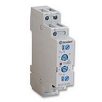
... Series - Modular Light Dependent Relays Type 11.01 is suitable for use on staircases and in entrance halls. Selector with 3 positions: - high range (threshold setting 20...1000lx) - low range (threshold setting 1...30lx) - continuous light (particularly interesting for the Test at the first installation). - Type 11.71: with 1 CO contact and with 12 ...
Page 135
... Series - Modular Light Dependent Relays 16 A ORDERING INFORMATION Example series light dependent relay “zero hysteresis” with contact and 35 mm rail mounting, with 230 V AC supply Series Type rail (EN 50022) mounting, “zero hysteresis” rail (EN 50022) mounting No. of poles pole TECHNICAL DATA ...
Page 136
Two types available: - type 12.01 - mechanical daily time switch - type 12.21/22 - digital weekly time switch - 35.8 mm wide - 35 mm rail (EN 50022) mount - Internal battery for the set up without supply ...
Page 137
ORDERING INFORMATION Example series, mechanical daily time switch supply voltage 230 V AC Series Type 0 = Daily 2 = Weekly No. of poles CO, 16 ...
Page 138
... Electrical life at rated load in AC1 Maximum impuls duration Dielectric strenght between: open contacts V AC supply contacts V AC Ambient temperature range Protection category Approvals: (according to type) 136 13 Series - Electronic Step Relays 13.01 - Low voltage supply 12- Step or monostable relay - Panel mount - 35 mm rail mount - Screw terminals ...
Page 139
... Type 13.01 Bistable (step) wiring diagram Type 13.71 3 wire connection 13 Series - Electronic Step Relays Supply voltage 012 = 12 V AC/DC 024 = 24 V AC/DC 125 = 110…125 V AC 230 = 230…240 V AC 230 = 230 VAC (13.71 only) Supply version (50/60 Hz)/DC (for 13.01.0.012 and 13.01.0.024 only (50/60 Hz) 13 ...
Page 140
One module (17.4 mm) wide - Time range from min - Can be used with illuminated push - buttons - Suitable for wiring systems - LED indicators - 35 mm rail (EN ...
Page 141
ORDERING INFORMATION Example series single module relay with a single phase switch contact, with supply rated at 230 V AC Series Type rail (EN 50022) ...
Page 142
FUNCTIONS Type 14.01.8.230 The following functions are selected by means of a DIP SWITCH: Timing step relay Push-button Relay T Light constantly ON Push-button Relay Type 14.71.8.230 The following functions are selected by means of a SELECTOR SWITCH: Light constantly ...
Page 143
... Electrical life at rated load in AC1 cycles Maximum impulse duration Insulation between coil and contacts (1.2/50µs) kV Ambient temperature range Protection category Approvals: (according to type) 20 Series - Modular Step Relays 16 A 20.21 20.22, 24, 26 Single phase switch Double phase switch - 35 mm rail mount - 35 mm rail mount ...
Page 144
... POWER LOST TO THE ENVIRONMENT - with rated current MAX WIRE SIZE mm AWG 1x12 / 2x14 SCREW TORQUE If the coil is operated for a prolonged period of time, adaquate ventilation of the relays must be provided, for example leaving a gap of about 9mm between pairs of relays. COIL SPECIFICATIONS AC VERSION DATA Nominal Coil code ...
Page 145
... Type 026.00 Sealed version, 7.5 cm insulated and flexible terminals. ACCESSORIES Sheet of marker tags (24 tags) 020.24 20 Series - Modular Step Relays Example of wiring diagram of type 026.00 This module is necessary if using maximum of 15 illuminated pushbuttons (1.5 mA max, 230 V AC) in the switching input circuit. It must be be connected in parallel to the coil of the relay (see diagram) ...
Page 146
... Electrical life at rated load in AC1 22 Maximum impulse duration Insulation between coil and contacts (1.2/50µs) kV Ambient temperature range Protection category Approvals: (according to type) 144 22 Series - Modular Monostable Relays 20 A 22.21 - Single phase switch Double phase switch rail mount - 35 mm rail mount A1 1 ...
Page 147
... Electrical life at rated load in AC1 cycles Maximum impulse duration Insulation between coil and contacts (1.2/50µs) kV Ambient temperature range Protection category Approvals: (according to type) 22 Series - Modular Monostable Relays 20 A 22.23 - Double phase switch - Double phase switch rail mount - 35 mm rail mount ...
Page 148
... MAX WIRE SIZE mm AWG 1x12 / 2x14 SCREW TORQUE If the coil is operated for a prolonged period of time, adaquate ventilation of the relays must be provided, for example leaving a gap of about 9mm between pairs of relays. COIL SPECIFICATIONS AC VERSION DATA Nominal Coil ...
Page 149
... Mechanical life cycles Electrical life at rated load in AC1 cycles Maximum impulse duration Insulation between coil and contacts (1.2/50µs) kV Ambient temperature range Protection category Approvals: (according to type) 26 Series - Step Relays 10 A 26.01 26.02,04,06,08 - Single phase switch Double phase switch 26.01 Ø 3.5 39 ...
Page 150
... min 8.012 9.6 24 8.024 19.2 48 8.048 38.4 110 8.110 88 121 230 8.230 184 253 26 148 26 Series - Step Relays 3,500 2,000 2,000 26.01 W 0.9 solid cable stranded cable 2 1x4 / 2x2.5 1x2.5 / 2x2.5 1x14 / 2x14 Nm 0.8 Resistance Consumption (50Hz) max 13.2 ...
Page 151
... MODULE FOR ILLUMINATED PUSH-BUTTONS 32 25 Ø 0.8 Type 026.00 Sealed version, 7.5 cm insulated and flexible terminals. 26 Series - Step Relays 10 A Example of wiring for control application. 13 Example of wiring diagram of type 026.00 This module is necessary if using maximum of 15 illuminated pushbuttons (1.5 mA max, 230 V AC) in the switching input circuit ...
Page 152
... Mechanical life Electrical life at rated load in AC1 Maximum impulse duration Insulation between coil and contacts (1.2/50µs) kV Ambient temperature range 27 Protection category Approvals: (according to type) 150 27 Series - Step Relays 10 A 27.01 - Single phase switch Double phase switch A1/1 32 Ø 3.2 21.5 ...
Page 153
... ACCESSORIES MODULE FOR ILLUMINATED PUSH-BUTTONS 12 20.5 Type 027.00 This module is necessary if using maximum of 15 illuminated push-buttons (1 mA max, 230 V AC) in the switching input circuit. It must be pluged directly into the relay. 27 Series - Step Relays Coil voltage see coil specifications Coil version ...
Page 154
...
Page 155
... Hz frequency. The tolerance for coil resistance, nominal absorption and rated power values is ± 10%. WORKING CONDITIONS - Unless expressly indicated otherwise, all relays are suitable for 100% Duty Cycle and all the AC coil relays are suitable for 50 and 60 Hz frequency. ...
Page 156
TERMINOLOGY & DEFINITIONS All the following terms indicated in the catalogue are commonly used in technical language. However, occasionally, National European or International Standards may prescribe the use of different terms, in which case this will be mentioned in the ...
Page 157
... The appropriate Application Category will also define the voltage and current levels used to measure the contact resistance. All Finder relays are category 3, with the exception of 30 series, which is category 2 ...
Page 158
... RATED COIL CONSUMPTION - The average value of coil current, when energised at nominal voltage. CONTROL CURRENT (Solid State Relays) - The nominal value of curent consumption of the input circuit, when supplied at nominal voltage. THERMAL TESTS - Calculation of the coil temperature rise ( T) is made by measuring the coil resistance in a controlled temperature oven (not ven- tilated) until a stable value is reached (no less than 0 ...
Page 159
... IEC 60664-1 Annex A, Table A.1. For all Finder relays a 100 % test is carried out with a 50 Hz, alternating voltage applied between all contacts and coil, between adjacent contacts and between open contacts. The leakage current must be less than 3 mA. ...
Page 160
... DUTY FACTOR (DF) - During cyclic operation the ratio between the energised time and one period. For continuous duty, DF =1. MECHANICAL LIFE - This test is performed by energising the coils of several relays at 8 cycles per second without any load applied to the con- tacts. It establishes the ultimate durability of the relay where electrical wear of the contacts is not an issue. The maximum Electrical Life may therefore approach the Mechanical Life where the electrical loading of the contacts is very small ...
Page 161
... For any terminals, a minimum cross-section of 0.2 mm According to EN 60204- permitted to introduce 2 or more wires into the same terminal. All Finder products are designed in such a way that each terminal can accept 2 or more wires. ...
Page 162
... It is therefore necessary to consider Finder products as not being indestructible under all circumstances. The user should pay attention to the disturbances in electrical systems and reduce as much as possible these disturbances. For example, employ arc suppression circuits on the contacts of switches, relays or contactors which otherwise might produce over-voltages when opening electrical circuits (particularly highly inductive or DC loads) ...
Page 163
... Sockets Relays 94.84.1 55.32, 55.34 CODE 99.80.9.024.99 99.80.9.060.99 99.80.9.220.99 99.80.0.024.98 99.80.0.060.98 99.80.0.230.98 99.80.0.024.59 99.80.0.060.59 99.80.0.230.59 99.80.3.000.00 99.80.0.024.09 99.80.0.060.09 99.80.0.230.09 99.80.8.230.07 i 161 ...
Page 164
... The relay release time increases insignificantly. R RESIDUAL CURRENT BYPASS MODULE Bypass modules are advisable if 110 or 230v AC relays show any tendency to fail to R release. Failure to release can be caused by residual currents from AC proximity switches or inductive coupling caused through long parallel lying AC control lines. ...
Page 165
... Finder.BR@findernet.com www.findernet.com FINDER SpA Via Drubiaglio 10040 ALMESE (TO) Tel. +39/011.9346211 Fax +39/011.9359079 Export@findernet.com Distributor FINDER reserves the right to alter characteristics at any time without notice. FINDER assumes no liability for damage to people or things, caused as a result of the incorrect use or application of its products. ® ...