80.91.0.240.0000 FINDER, 80.91.0.240.0000 Datasheet - Page 158
80.91.0.240.0000
Manufacturer Part Number
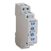
80.91.0.240.0000
Description
TIMER, MULTIFUNCTION
Manufacturer
FINDER
Datasheet
1.81.01.0.230.0000.pdf
(165 pages)
Specifications of 80.91.0.240.0000
Contact Configuration
SPCO
Nom Input Voltage
240V
Delay Time Range
0.1s To 20h
Adjustment Type
Screwdriver Slot
Relay Mounting
DIN Rail
Svhc
No SVHC (15-Dec-2010)
Coil Voltage Vac Nom
240V
Coil Voltage Max
240V


156
i
COIL (or INPUT or SUPPLY) SPECIFICATIONS
NOMINAL VOLTAGE - The nominal value of coil (or input or supply) voltage for which the relay has been designed, and for which operation is
intended. The operating and use characteristics are referred to the rated voltage.
RATED POWER - The DC power value (W) or the apparent AC power value (VA with closed armature) which is absorbed by the coil at 23°C and
at rated voltage. It is a short-time value (not steady-state).
OPERATING RANGE - The range of input voltage, in nominal voltage applications, in which the relay works in the whole range of ambient
temperatures, according to operating class:
In application where the coil voltage doesn’t meet the tolerances of nominal voltage, the diagrams “R” shows the relation of maximum coil voltage
permitted and pick-up voltage (without pre-energisation) versus ambient temperature.
NON-OPERATE VOLTAGE - The value of input voltage at which the relay will not operate (not specified in the catalogue).
MINIMUM PICK-UP VOLTAGE (Operate voltage) - The lowest value of applied voltage at which the relay will operate.
MAXIMUM VOLTAGE - The highest applied voltage that the relay can continuously withstand, dependent on ambient temperature (see “R”
diagrams).
HOLDING VOLTAGE (Non-release voltage) - The lowest value of coil voltage at which the relay (which has previously been energised with a
voltage within the operating range) will not drop-out.
MUST DROP-OUT VOLTAGE (Release voltage) - The value of coil voltage at which the relay (which had previously been energised with a
voltage within the operating range) will definitely drop-out.
RESISTANCE - The average value of the coil resistance under the standard prescribed condition of 23°C ambient.
RATED COIL CONSUMPTION - The average value of coil current, when energised at nominal voltage.
CONTROL CURRENT (Solid State Relays) - The nominal value of curent consumption of the input circuit, when supplied at nominal voltage.
THERMAL TESTS - Calculation of the coil temperature rise ( T) is made by measuring the coil resistance in a controlled temperature oven (not ven-
tilated) until a stable value is reached (no less than 0.5 K variation in 10 minutes).
That is: T = (R
INSULATION DATA
INSULATION COORDINATION (according to EN 61810-5 and IEC 60664-1)
In accordance with to EN 61810-5, the Insulation characteristics achieved by the relay can be described by just two characteristic parameters – the
Rated Impulse Voltage and the Degree of Pollution.
To ensure the correct Insulation Coordination between the relay and the application, the equipment designer (relay user) should establish the Rated
Impulse Withstand Voltage appropriate to his application, and the Pollution level for the micro environment in which the relay is situated. He should
then match (or coordinate) these two figures with the corresponding values given in the appropriate relay data.
To establish the appropriate Pollution degree and Rated impulse withstand voltage refer either to an appropriate Product Standard (which may be
mandatory for the particular type of equipment), or consider the tables below. Select the Rated impulse withstand voltage from a knowledge of the
Nominal Voltage of the Supply and a knowledge of the Over Voltage Category (as described in IEC60664-1).
release range
0
0 must drop-out voltage
- class 1: 0.8...1.1 U
- class 2: 0.85...1.1 U
2
- R
1
)/R
not operating range
1
x (234.5 + t
N
N
non operate voltage
1
) - (t
uncertain release zone
2
- t
1
)
DE-ENERGIZATION VOLTAGE
ENERGIZATION VOLTAGE
holding voltage
where: R
uncertain operating zone
GENERAL TECHNICAL INFORMATION
R
t
t
1
2
1
2
= initial resistance
= final resistance
= initial temperature
= final temperature
min pick-up voltage
operating range
operating range
nominal voltage maximum voltage
nominal voltage maximum voltage
Related parts for 80.91.0.240.0000
Image
Part Number
Description
Manufacturer
Datasheet
Request
R

Part Number:
Description:
JUMPER LINK, 20WAY
Manufacturer:
FINDER
Datasheet:


Part Number:
Description:
INTERFACE RELAY, SPDT-CO, 24VAC/DC
Manufacturer:
FINDER
Datasheet:
Part Number:
Description:
INTERFACE RELAY, SPDT-CO, 24VDC
Manufacturer:
FINDER
Datasheet:

Part Number:
Description:
RELAY, SCREW TERM, 6A, 12VAC/DC
Manufacturer:
FINDER
Datasheet:
Part Number:
Description:
RELAY, SCREW TERM, 6A, 48VAC/DC
Manufacturer:
FINDER
Datasheet:
Part Number:
Description:
RELAY, SCREW TERM, 6A, 125VAC/DC
Manufacturer:
FINDER
Datasheet:
Part Number:
Description:
RELAY, SCREW TERM, 6A, 240VAC/DC
Manufacturer:
FINDER
Datasheet:
Part Number:
Description:
RELAY, SCREW TERM, 6A, 6VDC
Manufacturer:
FINDER
Datasheet:
Part Number:
Description:
RELAY, SCREW TERM, 6A, 12VDC
Manufacturer:
FINDER
Datasheet:
Part Number:
Description:
RELAY, SCRW TER, DPDT, 8A, 24VAC/DC
Manufacturer:
FINDER
Datasheet:
Part Number:
Description:
RELAY, SCREW TERM, DPDT, 8A, 12VDC
Manufacturer:
FINDER
Datasheet:
Part Number:
Description:
RELAY, SCREW TERM, DPDT, 8A, 24VDC
Manufacturer:
FINDER
Datasheet:

Part Number:
Description:
RELAY, SCREWLESS, 6A, 24VDC
Manufacturer:
FINDER
Datasheet: