80.91.0.240.0000 FINDER, 80.91.0.240.0000 Datasheet - Page 157
80.91.0.240.0000
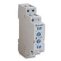
Manufacturer Part Number
80.91.0.240.0000
Description
TIMER, MULTIFUNCTION
Manufacturer
FINDER
Datasheet
1.81.01.0.230.0000.pdf
(165 pages)
Specifications of 80.91.0.240.0000
Contact Configuration
SPCO
Nom Input Voltage
240V
Delay Time Range
0.1s To 20h
Adjustment Type
Screwdriver Slot
Relay Mounting
DIN Rail
Svhc
No SVHC (15-Dec-2010)
Coil Voltage Vac Nom
240V
Coil Voltage Max
240V


ELECTRICAL LIFE TEST - An AC resistive load test (AC1category) conducted with relay coil (both AC and DC) supplied at rated voltage. Load
applied between all movable and NO contacts but without any load on the NC contacts, and vice-versa. These load life values are valid for relays
with standard contact material.
Switching frequency:
LOAD REDUCTION FACTOR VERSUS COS
corresponding to cos
fluorescent lamps.
TABLE 1
Load Category
* The switching voltage at the same current can be doubled by wiring 2 contacts in series.
CONTACT RESISTANCE - Measured, according to contact category (Table 2), at the external terminals of the relay. It is a statistical value, not
reproducible. It hasn’t any effect on relay reliability on most application. The typical value, measured with 24 V 100 mA, is 50 m .
TABLE 2
The effectiveness with which a relay contact can make an electrical circuit depends on several factors, such as the material used for the contact, its’
Application category
TABLE 3
Material
AgNi + Au
(Silver Nickel
(Silver Nickel)
AgCdO
(Silver Cadmium Oxide) - Good resistance to welding
AgSnO
(Silver Tin Oxide)
* It is necessary to refer to the maximum current values specified in the catalogue for each relay.
exposure to environmental pollution and its’ design etc.. Therefore, for reliable operation, it is necessary to specify a contact Application Category
that will define a particular relay’s switching capability in terms of maximum and minimum limits for contact voltage and current. The appropriate
Application Category will also define the voltage and current levels used to measure the contact resistance. All Finder relays are category 3, with
the exception of 30 series, which is category 2.
Gold plated)
AgNi
AC 14
AC 15
DC 13
AC 1
AC 3
AC 4
DC 1
2
- Contact categories according to EN60255-23
- Utilisation categories according to EN60947-4-1 and EN 60947-5-1
- Contact materials characteristics
3
0
1
2
AC single-phase
AC single-phase
AC single-phase
AC three-phase
AC three-phase
AC three-phase
Supply type
DC
DC
shall be multiplied by the rated current in order to define the maximum allowed current It is not valid for electric motors or
Property
- Silver-nickel base with a galvanic hard gold plating
- Gold is not attacked by industrial atmospheres
- With small loads, contact resistance is lower and
NOTE: 5 µm hard gold plating is completely different
from 0.2 µm gold flashing, which allows only
protection in storing, but no better performance in use.
- Standard contact material for most relay applications. - Resistive and slightly inductive loads
- High wear resistance
- Medium resistance to welding
- High wear resistance with higher AC loads
- Excellent resistance to welding
- Low material transfer in DC loads
of 5 µm typical thickness
more consistent compared to other materials.
0.8
0.6
0.4
1
All-or-nothing relays:
Step relays:
Application
Resistive or slightly Inductive AC loads.
Starting and stopping of Squirrel-cage motors. Reversing direction of rotation only after stopping motor.
Starting, Stopping and Reversing direction of rotation of Squirrel cage motors. Jogging (Inching). Regenerative braking (Plugging).
Resistive loads or slightly inductive DC loads.*
Control of small electromagnetic loads (<72 VA), power contactors, magnetic solenoid valves, and electromagnets.
Control of small electromagnetic loads (>72 VA), power contactors, magnetic solenoid valves, and electromagnets.
Control of electromagnetic loads, power contactors, magnetic solenoid valves, and electromagnets
0,03 < U < 60
5 < U < 600
Voltage (V)
0.8
5 < U < 250
U < 0,03
0.6
cos
- For AC inductive loads (such as solenoids, contactors coils, etc.) the reduction factor
0.4
k
coil 900 cycles/h - contact 900 cycles/h (2s ON - 2s OFF)
coil 900 cycles/h - contact 450 cycles/h (4s ON - 4s OFF)
0,1 < I < 100
0,01 < I < 0,1
Current (A)
0,1 < I <1
GENERAL TECHNICAL INFORMATION
I < 0.01
0.2
Typical application*
Wide range applications:
- Small load range (where gold plating erodes very little) from
- Middle load range where gold plating erodes after several
NOTE: for switching lower loads, typically 1mW (0.1V 1mA),
(for example in measuring instruments), it is recommended to
connect 2 contacts in parallel.
- Rated current up to 12 A
- Inrush current up to 25 A
- Inductive and motor loads
- Rated current up to 30 A
- Inrush current up to 50 A
- Lamp and capacitive loads
- Very high Inrush current (up to 120 A) loads
50 mW (5V 2mA) up to 1.5 W/24 V (resistive load).
operations and the property of basic AgNi becomes dominant.
Contact Resistance Measurement (IEC 61810-7)
> 30 mV
100 mV
24 V
24 V
1000 mA
100 mA
10 mA
10 mA
155
i
Related parts for 80.91.0.240.0000
Image
Part Number
Description
Manufacturer
Datasheet
Request
R

Part Number:
Description:
JUMPER LINK, 20WAY
Manufacturer:
FINDER
Datasheet:


Part Number:
Description:
INTERFACE RELAY, SPDT-CO, 24VAC/DC
Manufacturer:
FINDER
Datasheet:
Part Number:
Description:
INTERFACE RELAY, SPDT-CO, 24VDC
Manufacturer:
FINDER
Datasheet:

Part Number:
Description:
RELAY, SCREW TERM, 6A, 12VAC/DC
Manufacturer:
FINDER
Datasheet:
Part Number:
Description:
RELAY, SCREW TERM, 6A, 48VAC/DC
Manufacturer:
FINDER
Datasheet:
Part Number:
Description:
RELAY, SCREW TERM, 6A, 125VAC/DC
Manufacturer:
FINDER
Datasheet:
Part Number:
Description:
RELAY, SCREW TERM, 6A, 240VAC/DC
Manufacturer:
FINDER
Datasheet:
Part Number:
Description:
RELAY, SCREW TERM, 6A, 6VDC
Manufacturer:
FINDER
Datasheet:
Part Number:
Description:
RELAY, SCREW TERM, 6A, 12VDC
Manufacturer:
FINDER
Datasheet:
Part Number:
Description:
RELAY, SCRW TER, DPDT, 8A, 24VAC/DC
Manufacturer:
FINDER
Datasheet:
Part Number:
Description:
RELAY, SCREW TERM, DPDT, 8A, 12VDC
Manufacturer:
FINDER
Datasheet:
Part Number:
Description:
RELAY, SCREW TERM, DPDT, 8A, 24VDC
Manufacturer:
FINDER
Datasheet:

Part Number:
Description:
RELAY, SCREWLESS, 6A, 24VDC
Manufacturer:
FINDER
Datasheet: