80.91.0.240.0000 FINDER, 80.91.0.240.0000 Datasheet - Page 100
80.91.0.240.0000
Manufacturer Part Number
80.91.0.240.0000
Description
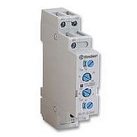
TIMER, MULTIFUNCTION
Manufacturer
FINDER
Datasheet
1.81.01.0.230.0000.pdf
(165 pages)
Specifications of 80.91.0.240.0000
Contact Configuration
SPCO
Nom Input Voltage
240V
Delay Time Range
0.1s To 20h
Adjustment Type
Screwdriver Slot
Relay Mounting
DIN Rail
Svhc
No SVHC (15-Dec-2010)
Coil Voltage Vac Nom
240V
Coil Voltage Max
240V


81
98
**Reset
**Reset
FUNCTIONS
**Reset facility is
Wiring diagram
Without signal START
With signal START
RESET
Function (R)
In each and every
function and time
scale, the timer is
immediately
released when the
reset switch is
depressed.
* Terminals R, X & S
**Reset facility is
L/+
L/+
must not be directly
connected to the
timer supply voltage,
but they should be
considered to be a
supply voltage
potential for the
purposes of
insulation.
optional
A1
optional
A1
R X
R X
A2
A2
S
*Start
S
N/–
N/–
18 15
18 15
16
16
U = Supply voltage
S = Signal switch
C = Output contact
R = RESET
Without signal Start= Start via contact in supply line (A1).
With signal Start = Start via contact into control terminal (S-X).
1
2
3
1
2
3
1
2
3
1
2
3
1
2
3
1
2
3
1
2
3
1
2
3
1
2
3
U
C
U
C
S
U
C
U
C
U
S
C
U
C
C
S
U
S
R
C
U
U
R
C
T
T
T
T
T
T
T
T
T
T
81 Series - Multi-function Modular Timer 16 A
T
Green
T
T
t<T
T
T
T
T
T
LED
t<T
T
T
T
Red
T
t<T
T
T
t<T
t<T
T
t<T
(EE)
Power is permenently applied to the timer.
On opening of the Signal Switch (S) the output contacts transfer,
and remain so for the duration of the preset delay, after which
they reset.
Depressing the Signal Reset Switch terminates the
interval time.
To re-start, it is necessary to depress the Signal Switch again.
Example: ON pulse function.
(AI)
Apply power to timer. Output contacts transfer after preset time
has elapsed. Reset occurs when power is removed.
(DI)
Apply power to timer. Output contacts transfer immediately.
After the preset time has elapsed, contacts reset.
(SW)
Apply power to timer. Output contacts transfer immediately and
cycle between ON and OFF for as long as power is applied.
The ratio is 1:1 (time on = time off).
(SP)
Apply power to timer. Output contacts transfer after time T has
elapsed and cycle between OFF and ON for as long as power is
applied. The ratio is 1:1 (time on = time off).
(BE)
Power is permenently applied to the timer.
The output contacts transfer immediately on closure of the Signal
Switch (S). Opening the Signal Switch initiates the preset delay,
after which time the output contacts reset.
(DE)
Power is permenently applied to the timer.
On momentary or maintained closure of Signal Switch (S),
the output contacts transfer, and remain so for the duration of
the preset delay, after which they reset.
On depressing the Signal Reset Switch the timer is
immediately released.
Releasing the Signal Reset Switch reactivates the function.
Example: ON delay function.
ON delay.
ON pulse.
Signal OFF pulse.
Signal OFF delay.
Symmetrical recycler: OFF start.
Signal ON pulse.
voltage
Supply
Symmetrical recycler: ON start.
OFF
ON
ON
NO output
contact
Closed
Open
Open
15 - 18
15 - 18
15 - 16
Open
Contacts
15 - 16
15 - 16
15 - 18
Closed
Related parts for 80.91.0.240.0000
Image
Part Number
Description
Manufacturer
Datasheet
Request
R

Part Number:
Description:
JUMPER LINK, 20WAY
Manufacturer:
FINDER
Datasheet:


Part Number:
Description:
INTERFACE RELAY, SPDT-CO, 24VAC/DC
Manufacturer:
FINDER
Datasheet:
Part Number:
Description:
INTERFACE RELAY, SPDT-CO, 24VDC
Manufacturer:
FINDER
Datasheet:

Part Number:
Description:
RELAY, SCREW TERM, 6A, 12VAC/DC
Manufacturer:
FINDER
Datasheet:
Part Number:
Description:
RELAY, SCREW TERM, 6A, 48VAC/DC
Manufacturer:
FINDER
Datasheet:
Part Number:
Description:
RELAY, SCREW TERM, 6A, 125VAC/DC
Manufacturer:
FINDER
Datasheet:
Part Number:
Description:
RELAY, SCREW TERM, 6A, 240VAC/DC
Manufacturer:
FINDER
Datasheet:
Part Number:
Description:
RELAY, SCREW TERM, 6A, 6VDC
Manufacturer:
FINDER
Datasheet:
Part Number:
Description:
RELAY, SCREW TERM, 6A, 12VDC
Manufacturer:
FINDER
Datasheet:
Part Number:
Description:
RELAY, SCRW TER, DPDT, 8A, 24VAC/DC
Manufacturer:
FINDER
Datasheet:
Part Number:
Description:
RELAY, SCREW TERM, DPDT, 8A, 12VDC
Manufacturer:
FINDER
Datasheet:
Part Number:
Description:
RELAY, SCREW TERM, DPDT, 8A, 24VDC
Manufacturer:
FINDER
Datasheet:

Part Number:
Description:
RELAY, SCREWLESS, 6A, 24VDC
Manufacturer:
FINDER
Datasheet: