80.91.0.240.0000 FINDER, 80.91.0.240.0000 Datasheet - Page 155
80.91.0.240.0000
Manufacturer Part Number
80.91.0.240.0000
Description
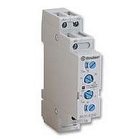
TIMER, MULTIFUNCTION
Manufacturer
FINDER
Datasheet
1.81.01.0.230.0000.pdf
(165 pages)
Specifications of 80.91.0.240.0000
Contact Configuration
SPCO
Nom Input Voltage
240V
Delay Time Range
0.1s To 20h
Adjustment Type
Screwdriver Slot
Relay Mounting
DIN Rail
Svhc
No SVHC (15-Dec-2010)
Coil Voltage Vac Nom
240V
Coil Voltage Max
240V


REFERENCE STANDARDS AND VALUES
Unless expressly indicated otherwise, the products shown in this catalogue are designed and manufactured according to the requirements of the
following European and International Standards:
- EN 61810-1, EN 61810-5, IEC 61810-7, EN 60255-23 for all-or-nothing (elementary) relays
- EN 61812-1 for timers
- EN 60669-1 and EN 60669-2-2 for electromechanical step relays
- EN 60669-1, EN 60669-2-1 and EN 60669-2-3 for electronic step relays and staircase switches
- EN 60065 for light-dependent relays
Other standards, used as reference for double insulation, are:
- VDE 0106 as basic standard
- EN 60335 (VDE 0700) for domestic appliances, prescribing 8mm creepage and clearance between coil and contacts
- EN 50178 (VDE 0160) for industrial appliances, prescribing 5.5 mm clearance and 6.4…8 mm creepage between coil and contacts
According to EN 61810-1, all technical data is specified under standard conditions of 23°C ambient temperature, 96 kPa pressure, 50%
humidity, clean air and 50 Hz frequency. The tolerance for coil resistance, nominal absorption and rated power values is ± 10%.
WORKING CONDITIONS
- Unless expressly indicated otherwise, all relays are suitable for 100% Duty Cycle and all the AC coil relays are suitable for 50 and 60 Hz
- Environmental conditions causing condensation or ice formation in the relay are not permitted.
- Overvoltage protection (varistor for AC, diode for DC) is recommended in parallel with the coil for nominal voltages
- When relay coils are controlled via a proximity switch, or via cables having length > 10m, the use of a “residual current bypass“ module in
GUIDELINES FOR AUTOMATIC FLOW SOLDER PROCESSES
In general, an automatic flow solder process consists of the following stages:
RELAY MOUNTING - Ensure that the relay terminals are straight and enter the PC board perpendicular to the PC board. For each relay, the
catalogue illustrates the necessary PC board pattern (copper side view).
FLUX APPLICATION - This is a particularly delicate process. If the relay is not sealed, flux may penetrate the relay due to capillary forces
changing its performance and functionality.
Whether using foam or spray fluxing methods, ensure that flux is applied sparingly and evenly and does not flood through to the component side
of the PC board.
By following the above precautions, and assuming the use of alcohol or water based fluxes, it is possible to satisfactorily use relays with protection
category RT II.
PREHEATING - Set the preheat time and heat to just achieve the effective evaporation of the flux, taking care not to exceed a component side
temperature of 100°C (212°F).
SOLDERING - Set the height of the molten solder wave such that the PC board is not flooded with solder.
Ensure the solder temperature and time are kept to 250°C (482°F) and 3 seconds maximum.
CLEANING - The use of modern “no-clean” flux avoids the necessity of washing the PC board. In special cases where the PC board must be
washed the use of wash-tight relays (option 0001 - RT III) is strongly recommended. Even so, avoid washing the relay itself, particularly with
aggressive solvents or in cycles using low temperature water, as this may cause thermal shock to the PC board components.
frequency.
40, 41, 44 series.
parallel with the coil is recommended.
GENERAL TECHNICAL INFORMATION
110 V for the relays of
153
i
Related parts for 80.91.0.240.0000
Image
Part Number
Description
Manufacturer
Datasheet
Request
R

Part Number:
Description:
JUMPER LINK, 20WAY
Manufacturer:
FINDER
Datasheet:


Part Number:
Description:
INTERFACE RELAY, SPDT-CO, 24VAC/DC
Manufacturer:
FINDER
Datasheet:
Part Number:
Description:
INTERFACE RELAY, SPDT-CO, 24VDC
Manufacturer:
FINDER
Datasheet:

Part Number:
Description:
RELAY, SCREW TERM, 6A, 12VAC/DC
Manufacturer:
FINDER
Datasheet:
Part Number:
Description:
RELAY, SCREW TERM, 6A, 48VAC/DC
Manufacturer:
FINDER
Datasheet:
Part Number:
Description:
RELAY, SCREW TERM, 6A, 125VAC/DC
Manufacturer:
FINDER
Datasheet:
Part Number:
Description:
RELAY, SCREW TERM, 6A, 240VAC/DC
Manufacturer:
FINDER
Datasheet:
Part Number:
Description:
RELAY, SCREW TERM, 6A, 6VDC
Manufacturer:
FINDER
Datasheet:
Part Number:
Description:
RELAY, SCREW TERM, 6A, 12VDC
Manufacturer:
FINDER
Datasheet:
Part Number:
Description:
RELAY, SCRW TER, DPDT, 8A, 24VAC/DC
Manufacturer:
FINDER
Datasheet:
Part Number:
Description:
RELAY, SCREW TERM, DPDT, 8A, 12VDC
Manufacturer:
FINDER
Datasheet:
Part Number:
Description:
RELAY, SCREW TERM, DPDT, 8A, 24VDC
Manufacturer:
FINDER
Datasheet:

Part Number:
Description:
RELAY, SCREWLESS, 6A, 24VDC
Manufacturer:
FINDER
Datasheet: