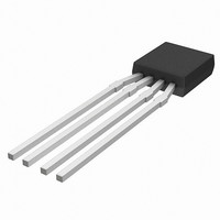
KMZ10C,112 NXP Semiconductors, KMZ10C,112 Datasheet - Page 27

KMZ10C,112
Manufacturer Part Number
KMZ10C,112
Description
IC MAGNETIC FIELD SENSOR SOT195
Manufacturer
NXP Semiconductors
Type
Special Purposer
Specifications of KMZ10C,112
Sensing Range
2mV/V
Voltage - Supply
5 V ~ 10 V
Output Type
Analog
Operating Temperature
-40°C ~ 150°C
Package / Case
SOT-195
Mounting Style
SMD/SMT
Maximum Operating Temperature
+ 150 C
Minimum Operating Temperature
- 40 C
Supply Voltage (min)
5 V
Supply Voltage (max)
10 V
Operating Temperature (min)
-40C
Operating Supply Voltage (typ)
5V
Lead Free Status / RoHS Status
Lead free / RoHS Compliant
Current - Supply
-
Current - Output (max)
-
Features
-
Lead Free Status / Rohs Status
Lead free / RoHS Compliant
Other names
933698480112
KMZ10C T/R
KMZ10C T/R
KMZ10C T/R
KMZ10C T/R
Philips Semiconductors
Both of the sensors deliver a single sinewave when rotated
in the Earth’s geomagnetic field (see Fig.29). This two
dimensional compass is sensitive to the angle
the Earth’s surface and the measurement plane of the
sensors: a change in this angle will change the alignment
between the sensitivity axis of the sensor and the Earth’s
field, and therefore affect sensor output. This effect, similar
to that seen in conventional compasses, can be clearly
observed in automotive applications, when a car is going
up- or downhill. High precision systems eliminate this
problem using a three dimensional compass and a gravity
sensor.
Table 5 Typical disturbances in compass systems for
Various levels of complexity can be incorporated in the
drive circuit, to include the various compensation
techniques described earlier in this chapter, depending on
the level of accuracy required and expected environmental
1998 Jun 12
handbook, full pagewidth
Zürich
Hamburg
Anchorage
Singapore
Tokyo
Magnetic field sensors
LOCATION
different angles
COMPASS 1
DIRECTION
SENSITIVE
12.5
9.7
1.5
5.7
17
5
Fig.29 Simplified block diagram of an electronic compass.
ANGLE
18.8
23.8
31.2
11.2
2.9
10
COMPASS 2
DIRECTION
SENSITIVE
between
26.9
33.3
42.1
16.5
4.3
15
27
V o2
V o1
influences. A basic and a high-end compass example are
described below.
A. Simple 8-segment compass
The main function of a simple compass application is to
purely indicate direction (N, NE, E, etc.). This basic
functionality is typically found in simple navigation aids
where, for example, car drivers may require only an
indication of their orientation and not an accurate
indication of their direction. For such simple application
set-ups, the accuracy produced by the sensor electronics
need only be of the order of 3 .
In such a simple compass application, the compass may
be required only to display the eight major compass
directions. In this case, the two output signals can be
compared with each other to achieve three digital signals
(Fig.31). These provide the basic N, S, E, W information
while a third, inverted sensor signal determines whether
the sensor signal is changing positively or negatively and
this is included in the comparison, to distinguish between
the eight positions on the compass. Simple comparators
can be used to obtain three digital signals, which drive a
display unit via a multiplexer.
Note: Figure 30 shows the principles of a typical compass
sensor set-up and for maximum clarity, compensation and
flipping coils are shown separately. Of course the KMZ51,
which has compensation and flipping coils incorporated
into the sensor housing, would be used in a real-life
application.
MBH623
V o2
V o1
General


