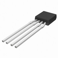
KMZ10C,112 NXP Semiconductors, KMZ10C,112 Datasheet - Page 29

KMZ10C,112
Manufacturer Part Number
KMZ10C,112
Description
IC MAGNETIC FIELD SENSOR SOT195
Manufacturer
NXP Semiconductors
Type
Special Purposer
Specifications of KMZ10C,112
Sensing Range
2mV/V
Voltage - Supply
5 V ~ 10 V
Output Type
Analog
Operating Temperature
-40°C ~ 150°C
Package / Case
SOT-195
Mounting Style
SMD/SMT
Maximum Operating Temperature
+ 150 C
Minimum Operating Temperature
- 40 C
Supply Voltage (min)
5 V
Supply Voltage (max)
10 V
Operating Temperature (min)
-40C
Operating Supply Voltage (typ)
5V
Lead Free Status / RoHS Status
Lead free / RoHS Compliant
Current - Supply
-
Current - Output (max)
-
Features
-
Lead Free Status / Rohs Status
Lead free / RoHS Compliant
Other names
933698480112
KMZ10C T/R
KMZ10C T/R
KMZ10C T/R
KMZ10C T/R
Philips Semiconductors
B. High-end compass
Compass resolution can be increased from the basic eight
by adapting the evaluation circuit and using a
microcontroller to calculate the arctan function of the ratio
of the two signals to determine the angle. The resolution of
the compass then depends on the microcontroller and the
A/D converters used. The use of a microcontroller also
enables additional functionality, such as storing a
reference direction or eliminating magnetic influences from
encapsulation or other magnetic components.
Simple alignment using opposite directions
Electronic compasses need calibrating to eliminate the
effects of these extraneous fields produced, for example,
by the compass casing. The simplest method is known as
Bi-directional Calibration. Requiring no external calibration
devices, in this technique the output is measured twice
with each measurement shifted by 180 . From this, the
x- and y- components of the extraneous field can be
determined and simply compensated for by applying the
appropriate current to the coils, synthesizing a
compensation field.
1998 Jun 12
Magnetic field sensors
Fig.32 Two-dimensional vector space.
interference
field
measured
field
3
coordinates
2
H y
1
3
2
1
2
3
1
earth's field
2
coordinates
3
MLC759
H x
29
Continuous alignment
With high-end compass applications, the microcontroller
can also be used to adjust the calibration of the compass
continually. This is especially useful in automotive
compasses, eliminating the need for manual
re-adjustment according to variable vehicle load.
Compass test units
For test purposes, Philips designed an SMD board
(Figs 34 and 35) with the following parameters:
An SMD compass sensor test unit was rotated in an Earth
field rotational unit, resulting in the test-diagram shown in
Fig.36.
Note: U
need to be provided externally.
Supply: 10 V
Current: 25 mA (typ.)
V
Load: >10 k
I
Noise: 0.05 A/m
Range: 100 A/m
Load: <70
Bandwidth: 10 Hz.
O (x,y)
O (x,y)
2nd measurement
: 62.5 A per A/m (5 mA/Gauss) (I
ref
1st measurement
Fig.33 Measured fields in vector space.
: 30 mV per A/m (V
is internally generated on the board, it does not
(<500
3
interference
field vector
coordinates
2
at V
H y
1
CC
x
, V
= 16 V)
y
3
2
1
1
2
3
1
V
earth's field
vector
ref
2
)
MLC761
coordinates
x
3
, I
General
y
H x
V
ref
)


