IXA20IF1200HB IXYS SEMICONDUCTOR, IXA20IF1200HB Datasheet
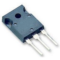
IGBT,1200V,38A,TO-247

IXA20IF1200HB

Manufacturer Part Number
IXA20IF1200HB
Description
IGBT,1200V,38A,TO-247
Manufacturer
IXYS SEMICONDUCTOR
Datasheet

Specifications of IXA20IF1200HB

Transistor Type
IGBT
Dc Collector Current
38A
Collector Emitter Voltage Vces
2.1V
Power Dissipation Max
165W
Collector Emitter Voltage V(br)ceo
1.2kV
Operating Temperature Range
-55°C To +150°C
Transistor
RoHS Compliant
Transistor Case Style
TO-247
Rohs Compliant
Yes
Power Dissipation Pd
165W

Available stocks

Company
Part Number
Manufacturer
Quantity
Price
Part Number:
IXA20IF1200HB
Quantity:
309
Part Number:
IXA20IF1200HB
Quantity:
309
XPT IGBT
Copack
Part number
IXA20IF1200HB
● Easy paralleling due to the positive temperature
● Rugged XPT design (Xtreme light Punch Through)
● Thin wafer technology combined with the XPT design
● SONIC™ diode
Symbol
V
V
I
P
I
I
V
V
Q
t
t
t
t
E
E
RBSOA
SCSOA
t
I
R
IXYS reserves the right to change limits, conditions and dimensions.
© 2010 IXYS all rights reserved
Features / Advantages:
I
IGBT
C25
C
GES
SC
SC
CES
d(on)
d(off)
r
f
CES
GES
tot
CE(sat)
GE(th)
on
off
coefficient of the on-state voltage
results in:
- short circuit rated for 10 µsec.
- very low gate charge
- low EMI
- square RBSOA @ 3x Ic
results in a competitive low VCE(sat)
- fast and soft reverse recovery
- low operating forward voltage
100
thJC
Gon
Collector emitter saturation voltage
Total gate charge
Turn-on delay time
Current rise time
Turn-off delay time
Current fall time
Turn-off energy per pulse
Short circuit duration
Definition
Collector emitter voltage
Maximum DC gate voltage
Collector current
Total power dissipation
Collector emitter leakage current
Gate emitter leakage current
Gate emitter threshold voltage
Turn-on energy per pulse
Reverse bias safe operation area
Short circuit safe operation area
Short circuit current
Thermal resistance juntion to case
V
V = V
V
I =
I =
V
Inductive load
V
V
V
V
V
R =
Conditions
C
C
GE
CE
CE
CE
GE
CEK
CE
CE
GE
G
= 0 V
= 0 V; V = ±20 V
=
=
= ±15 V; R =
=
=
16
=
0.6
Applications:
● AC motor drives
● Solar inverter
● Medical equipment
● Uninterruptible power supply
● Air-conditioning systems
● Welding equipment
● Switched-mode and resonant-mode
● Inductive heating, cookers
600
600
Data according to IEC 60747and per diode unless otherwise specified
1200
900
CES
power supplies
56
A; V =
15
mA; V
Ω
V; V
V; I =
; V = 0 V
V;
V; V = ±15 V
GE
GE
; non-repetitive
V
GE
C
GE
GE
G
R =
GE
15
G
=
= V
15
15
56
V
CE
A
56
Ω
V; I =
(G) 1
Ω
C
15
C (2)
E (3)
A
T
T
T
T
T
T
T
T
T
T
T
T
VJ
VJ
C
C
VJ
VJ
VJ
VJ
VJ
VJ
VJ
VJ
= 25°C
=
= 125°C
= 25°C
= 25°C
= 25°C
=
= 25°C
=
= 25°C
=
= 125°C
125
125
125
100
● Housing: TO-247
I
V
V
Package:
●rIndustry standard outline
●rEpoxy meets UL 94V-0
●rRoHS compliant
°C
°C
°C
°C
C25
CES
CE(sat)typ
IXA20IF1200HB
min.
5.4
R a t i n g s
=
=
=
typ.
1.55
250
100
0.1
1.8
2.1
1.7
47
70
40
6
1200
max.
1200
1.8 V
0.76
165
500
±20
38
0.1
2.1
6.5
38
22
45
10
60
20100102a
A
V
Unit
K/W
mA
mA
mJ
mJ
nC
nA
ns
ns
ns
ns
µs
W
V
V
A
A
V
V
V
A
A

Related parts for IXA20IF1200HB

IXA20IF1200HB Summary of contents

Page 1

... 1200 V CEK V = 900 ± Ω non-repetitive G Data according to IEC 60747and per diode unless otherwise specified IXA20IF1200HB C25 1200 CES V 1 CE(sat)typ Package: ● Housing: TO-247 ●rIndustry standard outline ●rEpoxy meets UL 94V-0 ●rRoHS compliant min. typ. max. Unit = 25°C 1200 = 25°C ±20 = 25° ...

Page 2

... IXYS reserves the right to change limits, conditions and dimensions. © 2010 IXYS all rights reserved Conditions T = 25° 100 ° 600 / 400 A/µ Data according to IEC 60747and per diode unless otherwise specified IXA20IF1200HB Ratings min. typ. max 25°C 1.95 2 125 °C 1. 125 °C VJ 350 0.7 0.9 Ratings min ...

Page 3

... IXYS reserves the right to change limits, conditions and dimensions. © 2010 IXYS all rights reserved Conditions Part Name Marking on Product IXA20IF1200HB Similar Part Package IXA20I1200PB TO-220AB (3) Data according to IEC 60747and per diode unless otherwise specified IXA20IF1200HB Ratings min. typ. -55 -55 0.25 0.8 20 Part number I ...

Page 4

... S E1 IXYS reserves the right to change limits, conditions and dimensions. © 2010 IXYS all rights reserved Data according to IEC 60747and per diode unless otherwise specified IXA20IF1200HB Sym. Inches Millimeter min. max. min. A 0.185 0.209 4.70 A1 0.087 0.102 2.21 A2 0.059 0.098 1.50 D ...

Page 5

... E 2 [mJ [A] C Fig. 5 Typ. switching energy vs. collector current IXYS reserves the right to change limits, conditions and dimensions. © 2010 IXYS all rights reserved = 125° off Data according to IEC 60747and per diode unless otherwise specified IXA20IF1200HB 125° [ [V] CE Fig. 2 Typ. output characteristics ...

Page 6

... A 500 400 rr [ns] 300 200 100 600 700 vs. di/ thJC 20 A [K/ 0.1 600 700 versus di/dt rec Data according to IEC 60747and per diode unless otherwise specified IXA20IF1200HB 200 300 400 500 di /dt [A/µs] F Fig. 8 Typ. reverse recov.charge 200 300 400 ...

Related keywords