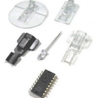
ADNK-6710 Avago Technologies US Inc., ADNK-6710 Datasheet - Page 10

ADNK-6710
Manufacturer Part Number
ADNK-6710
Description
Automatic Laser Calibration Tool
Manufacturer
Avago Technologies US Inc.
Datasheet
1.ADNK-6710.pdf
(12 pages)
Specifications of ADNK-6710
Tool Type
Laser Power Calibrator
Description/function
Optical Mouse Sensor Kit
Interface Type
USB
Product
Display Modules
Touch Panel
No Touch Panel
Lead Free Status / RoHS Status
Contains lead / RoHS non-compliant
For Use With/related Products
Laser Power Alignment
Lead Free Status / Rohs Status
No
command_write_eeprom – Called in process_command, will call Write_EEPROM routine to write value to the EEPROM
for a given memory address.
command_read_eeprom – Called in process_command, will call Read_EEPROM routine to read value from specific
EEPROM memory address.
command_write_sensor – Called in process_command, will call WriteSensor routine to write value to sensor register.
command_read_sensor – Called in process_command, will call ReadSensor routine to read register value from sensor.
command_test_sensor – This routine first reset the sensor and disable the laser. Then call AdjustLaser to load LP_CFG0
and LP_CFG1 value from EEPROM. Later, the sensor is set to continuous mode and laser is enabled.
command_reset_sensor – This routine reset the ADNS-6000 sensor.
command_echo – This routine echo back any data bytes upon received on INPUT endpoint 1.
finish_command – This routine format response result value and send to the USB OUTPUT endpoint 0 then return.
Laser Power Calibration Routine (Level 2)
ReadSensor – This routine read a register value from the sensor and stored the value into spi_data variable.
WriteSensor – This routine write value to the sensor for a given register address.
Read_EEPROM – This routine read a value from EEPROM memory and stored the value to spi_data variable.
Write_EEPROM – This routine write value to the EEPROM for a given memory address.
EEPROM_WREN – This routine enable the EEPROM chip-select pin.
AdjustLaser – called to calibrate the laser output power to the required 506uW. This will ensure that the laser output
power meets Class 1 eye safety. Customer must ensure that the correct LP_CFG0 and LP_CFG1 register values are written
into the registers for proper LASER operation.
enable_laser – Enable laser by writing value ‘0’ to configuration II - register (0x16) force_disable field.
disable_laser – Disable laser by writing value ‘1’ to configuration II register (0x16) force_disable field.
SetDCMode – Set the laser to continuous on mode (laser calibration mode).
Read_LP_CFG_REG – This routine reads calibrated LP_CFG0 and LP_CFG1 value from EEPROM which will be programmed
to sensor in AdjustLASER routine.
EEPROM
Figure 5.0 Read_LP_CFG_REG Routine Flowchart
0
Memory Address
0x00
0x0
CFG0_data Variable
READ_EEPROM at
CFG0_data Variable
READ_EEPROM at
Store Result to
Store Result to
Address 0x00
EEPROM_Init
Address 0x01
Description
Stored LP_CFG0 register value
Stored LP_CFG register value


