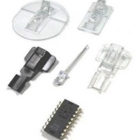
ADNK-6710 Avago Technologies US Inc., ADNK-6710 Datasheet - Page 3

ADNK-6710
Manufacturer Part Number
ADNK-6710
Description
Automatic Laser Calibration Tool
Manufacturer
Avago Technologies US Inc.
Datasheet
1.ADNK-6710.pdf
(12 pages)
Specifications of ADNK-6710
Tool Type
Laser Power Calibrator
Description/function
Optical Mouse Sensor Kit
Interface Type
USB
Product
Display Modules
Touch Panel
No Touch Panel
Lead Free Status / RoHS Status
Contains lead / RoHS non-compliant
For Use With/related Products
Laser Power Alignment
Lead Free Status / Rohs Status
No
3. Safety & Regulations
Regulatory Requirements
• Passes FCC B and worldwide analogous emission limits when assembled into a mouse with shielded cable and
• Passes IEC-1000-4-3 radiated susceptibility level when assembled into a mouse with shielded cable and following
• Passes EN61000-4-4/IEC801-4 EFT tests when assembled into a mouse with shielded cable and following Avago
• UL flammability level UL94 V-0.
• Provides sufficient ESD creepage/clearance distance to avoid discharge up to 15kV when assembled into a mouse
Eye Safety
The ADNS-6000 and the associated components in the schematic of Figure 6.0 are intended to comply with Class 1
Eye Safety Requirements of IEC 60825-1. Avago Technologies suggests that manufacturers perform testing to verify
eye safety on each mouse. It is also recommended to review possible single fault mechanisms beyond those described
below in the ADNS-6000 datasheet section.
Under normal conditions, the ADNS-6000 generates the drive current for the laser diode (ADNV-6340). In order to stay
below the Class 1 power requirements, resistor Rbin must be set at least as high as the value in the bin table, based
on the bin number of the laser diode and LP_CFG0 and LP_CFG1 must be programmed to appropriate values. Avago
Technologies recommends using the exact Rbin value specified in the bin table to ensure sufficient laser power for
navigation. The system comprised of the ADNS-6000 and ADNV-6340 is designed to maintain the output beam power
within Class 1 requirements over component manufacturing tolerances and the recommended temperature range
when adjusted per the procedure below and when implemented as shown in the recommended application circuit of
Figure 6.0. For more information, please refer to Eye Safety Application Note 5088.
LASER Power Adjustment Procedure
1. The ambient temperature should be 25C +/- 5C.
2. Set VDD3 to its permanent value.
3. Ensure that the laser drive is at 100% duty cycle by setting bit 6 of register 0x0A to 0.
4. Program the LP_CFG0 and LP_CFG1 registers to achieve an output power as close to 506uW as possible without
Good engineering practices should be used to guarantee performance, reliability and safety for the product design.
LASER Output Power
The laser beam output power as measured at the navigation surface plane is specified below. The following conditions
apply:
1. The system is adjusted according to the above procedure.
2. The system is operated within the recommended operating temperature range.
3. The VDD3 value is no greater than 50mV above its value at the time of adjustment.
4. No allowance for optical power meter accuracy is assumed.
following Avago Technologies recommendations.
Avago Technologies recommendations.
Technologies recommendations.
according to usage instructions above.
exceeding it.


