EVAL-AD7747EBZ Analog Devices Inc, EVAL-AD7747EBZ Datasheet - Page 15
EVAL-AD7747EBZ
Manufacturer Part Number
EVAL-AD7747EBZ
Description
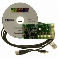
24-Bit Capacitance-to-Digital Converter Eval. Board
Manufacturer
Analog Devices Inc
Specifications of EVAL-AD7747EBZ
Silicon Manufacturer
Analog Devices
Application Sub Type
Capacitance-to-Digital Converter
Kit Application Type
Data Converter
Silicon Core Number
AD7747
Sensor Type
Touch, Capacitive
Interface
I²C
Voltage - Supply
2.7 V ~ 5.25 V
Embedded
No
Utilized Ic / Part
AD7747
Kit Contents
Board
Rohs Compliant
Yes
Lead Free Status / RoHS Status
Lead free / RoHS Compliant
Sensitivity
-
Sensing Range
-
Lead Free Status / RoHS Status
Lead free / RoHS Compliant, Lead free / RoHS Compliant
Available stocks
Company
Part Number
Manufacturer
Quantity
Price
Company:

Part Number:
EVAL-AD7747EBZ
Manufacturer:
Analog Devices Inc
Quantity:
135


STATUS REGISTER
Address Pointer 0x00, Read Only, Default Value 0x07
This register indicates the status of the converter. The status register can be read via the 2-wire serial interface to query a finished
conversion.
The RDY pin reflects the status of the RDY bit. Therefore, the RDY pin high-to-low transition can be used as an alternative indication of
the finished conversion.
Table 9. Status Register Bit Map
Bit
Mnemonic
Default
Table 10.
Bit
7 to 3
2
1
0
CAP DATA REGISTER
24 Bits, Address Pointer 0x01, 0x02, 0x03, Read-Only,
Default Value 0x000000
This register contains the capacitive channel output data. The
register is updated after finished conversion on the capacitive
channel, with one exception: When the serial interface read
operation from the Cap Data register is in progress, the data
register is not updated and the new capacitance conversion
result is lost.
The stop condition on the serial interface is considered to be the
end of the read operation. Therefore, to prevent data corruption,
all three bytes of the data register should be read sequentially
using the register address pointer auto-increment feature of the
serial interface.
To prevent losing some of the results, the Cap Data register
should be read before the next conversion on the capacitive
channel is finished.
The 0x000000 code represents negative full scale (−8.192 pF),
the 0x800000 code represents zero scale (0 pF), and the
0xFFFFFF code represents positive full scale (+8.192 pF).
Mnemonic
–
RDY
RDYVT
RDYCAP
Description
Not used, always read 0.
RDY = 0 indicates that conversion on the enabled channel(s) is complete and new unread data is available.
If both capacitive and voltage/temperature channels are enabled, the RDY bit is changed to 0 after conversion
on both channels is complete. The RDY bit returns to 1 either when data is read or prior to finishing the next
conversion. If, for example, only the capacitive channel is enabled, then the RDY bit reflects the RDYCAP bit.
RDYVT = 0 indicates that a conversion on the voltage/temperature channel is complete and new unread data
is available.
RDYCAP = 0 indicates that a conversion on the capacitive channel is complete and new unread data is available.
Bit 7
–
0
Bit 6
–
0
Bit 5
–
0
Rev. 0 | Page 15 of 28
Bit 4
–
0
VT DATA REGISTER
24 Bits, Address Pointer 0x04, 0x05, 0x06, Read-Only,
Default Value 0x000000
This register contains the voltage/temperature channel output
data. The register is updated after finished conversion on the
voltage channel or temperature channel, with one exception:
When the serial interface read operation from the VT Data
register is in progress, the data register is not updated and the
new voltage/temperature conversion result is lost.
The stop condition on the serial interface is considered to be the
end of the read operation. Therefore, to prevent data corruption,
all three bytes of the data register should be read sequentially
using the register address pointer auto-increment feature of the
serial interface.
For voltage input, Code 0 represents negative full scale (−V
the 0x800000 code represents zero scale (0 V), and the
0xFFFFFF code represents positive full scale (+V
To prevent losing some of the results, the VT Data register
should be read before the next conversion on the voltage/
temperature channel is complete.
For the temperature sensor, the temperature can be calculated
from code using the following equation:
Temperature (°C) = (Code/2048) − 4096
Bit 3
–
0
Bit 2
RDY
1
Bit 1
RDYVT
1
REF
).
Bit 0
RDYCAP
1
AD7747
REF
),
Related parts for EVAL-AD7747EBZ
Image
Part Number
Description
Manufacturer
Datasheet
Request
R


Part Number:
Description:
BOARD EVAL FOR SI270X-A
Manufacturer:
Silicon Laboratories Inc
Datasheet:

Part Number:
Description:
BUCK CONV REF DESIGN KIT IP1201
Manufacturer:
International Rectifier
Datasheet:
Part Number:
Description:
BOARD DEMO SYNC DUAL BUCK CNVTER
Manufacturer:
International Rectifier
Datasheet:
Part Number:
Description:
BOARD DEMO SYNC BUCK CONVETER
Manufacturer:
International Rectifier
Datasheet:

Part Number:
Description:
EVALBOARD/EB Omnidirectional microphone - Analog
Manufacturer:
Analog Devices
Datasheet:
Part Number:
Description:
EVALBOARD/EB Omnidirectional microphone - Analog
Manufacturer:
Analog Devices
Datasheet:


Part Number:
Description:
BOARD EVAL LED DRIVER LT3756
Manufacturer:
Linear Technology
Datasheet:

Part Number:
Description:
BOARD EVAL FOR AD7741/7742
Manufacturer:
Analog Devices Inc
Datasheet:

Part Number:
Description:
±1.7g Dual-Axis IMEMS Accelerometer Evaluation Board
Manufacturer:
Analog Devices Inc
Datasheet:

Part Number:
Description:
IC MULTIPLIER ANALOG 8-SOIC T/R
Manufacturer:
Analog Devices Inc
Datasheet:

Part Number:
Description:
IC ANALOG MULTIPLIER 8-DIP
Manufacturer:
Analog Devices Inc
Datasheet:
Part Number:
Description:
IC ANALOG MULTIPLIER 8-SOIC
Manufacturer:
Analog Devices Inc
Datasheet:
Part Number:
Description:
IC ANALOG MULTIPLIER 8-DIP
Manufacturer:
Analog Devices Inc
Datasheet: