EVAL-AD7747EBZ Analog Devices Inc, EVAL-AD7747EBZ Datasheet - Page 22
EVAL-AD7747EBZ
Manufacturer Part Number
EVAL-AD7747EBZ
Description
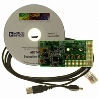
24-Bit Capacitance-to-Digital Converter Eval. Board
Manufacturer
Analog Devices Inc
Specifications of EVAL-AD7747EBZ
Silicon Manufacturer
Analog Devices
Application Sub Type
Capacitance-to-Digital Converter
Kit Application Type
Data Converter
Silicon Core Number
AD7747
Sensor Type
Touch, Capacitive
Interface
I²C
Voltage - Supply
2.7 V ~ 5.25 V
Embedded
No
Utilized Ic / Part
AD7747
Kit Contents
Board
Rohs Compliant
Yes
Lead Free Status / RoHS Status
Lead free / RoHS Compliant
Sensitivity
-
Sensing Range
-
Lead Free Status / RoHS Status
Lead free / RoHS Compliant, Lead free / RoHS Compliant
Available stocks
Company
Part Number
Manufacturer
Quantity
Price
Company:

Part Number:
EVAL-AD7747EBZ
Manufacturer:
Analog Devices Inc
Quantity:
135


AD7747
The CAPDAC can be understood as a negative capacitance
connected internally to the CIN pin. There are two independent
CAPDACs, one connected to the CIN(+) and the second con-
nected to the CIN(−). The relation between the capacitance
input and output data can be expressed as
The CAPDACs have a 6-bit resolution, monotonic transfer
function, are well matched to each other, and have a defined
temperature coefficient. The CAPDAC full range (absolute
value) is not factory calibrated and can vary up to ±20% with
the manufacturing process. See the Specifications section and
Figure 16 of the typical performance characteristics.
SINGLE-ENDED CAPACITIVE CONFIGURATION
The AD7747 can be used for interfacing to a single-ended
capacitive sensor. In this configuration the sensor should be
connected to one of the AD7747 CIN pins, for example CIN(+)
and the other pin should be left open circuit. Note that the
CAPDIFF bit in the Cap Setup register must be set to 1 at all
times for the correct operation.
It is recommended to guard the unused CIN input with the
active shield to ensure the best performance in terms of noise,
offset, and offset drift.
The CDC (without using the CAPDACs) measure the positive
(or the negative) input capacitance in the range of 0 pF to 8 pF
(see Figure 27).
The CAPDAC can be used for programmable shifting of the
input range. The example in Figure 28 shows how to use the full
±8 pF CDC span to measure capacitance between 0 pF to 16 pF.
DATA
C
0...16pF
C
0...8pF
X
X
Figure 28. Using CAPDAC in Single-Ended Configuration
Figure 27. CDC Single-Ended Input Configuration
≈
(
C
X
CIN(+)
CIN(–)
CIN(+)
CIN(–)
SHLD
−
SHLD
CAPDAC
CAPDIFF = 1
CAPDIFF = 1
CAPDAC(+)
OFF
CAPDAC(–)
OFF
CAPDAC(+)
8pF
CAPDAC(–)
0pF
(
+
)
) (
−
C
Y
−
CAPDAC
0...8pF
CDC
±8pF
CDC
0xFFFFFF
0x800000
0xFFFFFF
0x000000
(
−
TO
DATA
TO
DATA
)
)
Rev. 0 | Page 22 of 28
Figure 29 shows how to shift the input range further, up to
25 pF absolute value of capacitance connected to the CIN(+).
DIFFERENTIAL CAPACITIVE CONFIGURATION
When the AD7747 is used for interfacing to a differential
capacitive sensor, each of the two input capacitances, C
must be less than 8 pF (without using the CAPDACs) or must
be less than 25 pF and balanced by the CAPDACs. Balancing
by the CAPDACs means that both C
C
If the unbalanced capacitance connected to CIN pins is higher
than 8 pF, the CDC introduces a gain error, an offset error, and
nonlinearity error.
See the examples shown in Figure 30, Figure 31, and Figure 32.
Y
− CAPDAC(−) are less than 8 pF.
(17pF ± 4pF)
13...21pF
C
C
0...8pF
(17pF ± 8pF)
X
9...25pF
X
C
X
Figure 29. Using CAPDAC in Single-Ended Configuration
Figure 31. Using CAPDAC in Differential Configuration
Figure 30. CDC Differential Input Configuration
13...21pF
(17pF ± 4pF)
C
0...8pF
C
Y
Y
CIN(+)
CIN(–)
SHLD
CIN(+)
CIN(–)
SHLD
CIN(+)
CIN(–)
SHLD
CAPDIFF = 1
CAPDAC(+)
17pF
CAPDAC(–)
0pF
CAPDIFF = 1
CAPDIFF = 1
CAPDAC(+)
OFF
CAPDAC(–)
OFF
CAPDAC(+)
17pF
CAPDAC(–)
17pF
X
− CAPDAC(+) and
±8pF
CDC
±8pF
CDC
±8pF
CDC
0xFFFFFF
0x000000
0xFFFFFF
0x000000
0xFFFFFF
0x000000
TO
DATA
TO
DATA
TO
DATA
X
and C
Y,
Related parts for EVAL-AD7747EBZ
Image
Part Number
Description
Manufacturer
Datasheet
Request
R


Part Number:
Description:
BOARD EVAL FOR SI270X-A
Manufacturer:
Silicon Laboratories Inc
Datasheet:

Part Number:
Description:
BUCK CONV REF DESIGN KIT IP1201
Manufacturer:
International Rectifier
Datasheet:
Part Number:
Description:
BOARD DEMO SYNC DUAL BUCK CNVTER
Manufacturer:
International Rectifier
Datasheet:
Part Number:
Description:
BOARD DEMO SYNC BUCK CONVETER
Manufacturer:
International Rectifier
Datasheet:

Part Number:
Description:
EVALBOARD/EB Omnidirectional microphone - Analog
Manufacturer:
Analog Devices
Datasheet:
Part Number:
Description:
EVALBOARD/EB Omnidirectional microphone - Analog
Manufacturer:
Analog Devices
Datasheet:


Part Number:
Description:
BOARD EVAL LED DRIVER LT3756
Manufacturer:
Linear Technology
Datasheet:

Part Number:
Description:
BOARD EVAL FOR AD7741/7742
Manufacturer:
Analog Devices Inc
Datasheet:

Part Number:
Description:
±1.7g Dual-Axis IMEMS Accelerometer Evaluation Board
Manufacturer:
Analog Devices Inc
Datasheet:

Part Number:
Description:
IC MULTIPLIER ANALOG 8-SOIC T/R
Manufacturer:
Analog Devices Inc
Datasheet:

Part Number:
Description:
IC ANALOG MULTIPLIER 8-DIP
Manufacturer:
Analog Devices Inc
Datasheet:
Part Number:
Description:
IC ANALOG MULTIPLIER 8-SOIC
Manufacturer:
Analog Devices Inc
Datasheet:
Part Number:
Description:
IC ANALOG MULTIPLIER 8-DIP
Manufacturer:
Analog Devices Inc
Datasheet: