EM1-H0R0V-1N SENSIRION, EM1-H0R0V-1N Datasheet - Page 8
EM1-H0R0V-1N
Manufacturer Part Number
EM1-H0R0V-1N
Description
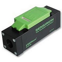
MASS FLOW METER, FOR GASES
Manufacturer
SENSIRION
Datasheet
1.EM1-H0R0V-1N.pdf
(17 pages)
Specifications of EM1-H0R0V-1N
Svhc
No SVHC (15-Dec-2010)
Air Flow Range
0 - 0.05 L/min
External Length / Height
104mm
External Width
33.7mm
Height
43.6mm
Length (imperial)
5.35"
Output Configuration
RS232/SPI
Output Type
RS232
Pressure Max
8bar
Supply Voltage Range Dc
7V To 18V
Supply Voltage Dc Max
18VDC
Rohs Compliant
Yes
Lead Free Status / RoHS Status
Lead free / RoHS Compliant


CMOSens
Figure 7: Byte sequence of one value
Because of the maximum range of 0x7852, the high
byte never will contain 0x7F. Therefore the worst case
is, if the lower byte contains 0x7F. In this special case,
0x7F appears three times in a row.
Example (val=7C 7F):
The best approach to find the sync in pseudo code:
if (buffer[ i ]=7F and buffer[i+1]=7F and buffer[i+2] <>
7F)
then buffer[i] and buffer[i+1] are sync bytes.
2.6 Serial Peripheral Interface (SPI)
To make measurement data available also for smaller
systems or to cascade several CMOSens
devices, the CMOSens
provides
configuration of the CMOSens
described in Section 3) has to be done using the RS232
port.
SPI Modes
There are two different SPI modes, namely the PUSH
and the GET mode. In PUSH mode, each time a value
is sent through RS232, the same value is sent by SPI
simultaneously. In GET mode, the buffered value is
sent immediately after /CS is pulled down by the user.
Important: Sensor has to be in GO mode for valid data
on SPI-Port.
Hardware
The internal SPI setup of the CMOSens
Flow Meter is shown in Figure 8. Figure 9 shows an
example of cascading four CMOSens
using a single microcontroller or a FPGA.
Note: With each additional sensor the capacitive load
will increase, causing an increase of the output fall/rise
time and an output signal deterioration.
www.sensirion.com
1. byte 2. byte 3. byte 4. byte
sync
0x7F
received string: 7F 7F 7C 7F 7F 7F 7C 7F
right sync:
wrong sync:
®
sync
0x7F
a
EM1 Mass Flow Meter for Gases
uni-directional
MSB
®
7F 7F 7C 7F 7F 7F 7C 7F
EM1 Mass Flow Meter
LSB
®
7F 7F 7F 7C
SPI
Mass Flow Meter (as
interface.
®
®
EM1 devices
Data Sheet EM1 - v 2.6 / October 2006
EM1 Mass
®
EM1
The
PIN 3
PIN 4
PIN 5
PIN 6
Figure 8: Internal CMOSens
Figure 9: Cascading four CMOSens
using the SPI interface.
SCK
The SCK synchronizes data transfer out of the device
through the MOSI line. Data on the MOSI pin is ready
after a falling edge of SCK. In every case, the
CMOSens
changed only by CMOSens
GET mode.
/CS
In PUSH mode, /CS is controlled by CMOSens
Before sending a new value, /CS goes low and after the
transfer of 16 data bits /CS goes high.
In GET mode, the user requests the last measured
value by pulling down /CS. After transfer, /CS has to be
released otherwise the same value will be sent
repeatedly.
MOSI
MOSI is the serial data output of the CMOSens
device. Data is clocked out on the rising edge SCK with
MSB first. This output goes into a high-impedance state
when the Mass Flow Meter is not selected.
MISO
The CMOSens
supports a uni-directional SPI protocol. Therefore, the
MISO pin should always left unconnected.
SERIAL CLOCK (SCK)
SPI
CHIP
SELECTION
DATA IN (MISO)
MOSI
MISO
SCK
(Serial Clock, Output)
(Chip Select, Input or Output)
(Master Out Slave In, Output)
(Master In Slave Out, Not Connected)
MASTER MCU
/CS
®
EM1 is master. That means, that SCK is
®
/CS0
/CS1
/CS2
/CS3
560
560
560
560
Mass Flow Meter firmware only
47 pF
GND
®
®
MFM SPI hardware.
Mass Flow Meter even in
®
EM1 devices
GND
+5 V
50 K
MICRO-
CONTROLLER
®
SCK
MOSI
/CS
SCK
MOSI
/CS
EM1 1...4
SCK
MOSI
/CS
SCK
MOSI
/CS
®
8 / 17
EM1.
EM1
Related parts for EM1-H0R0V-1N
Image
Part Number
Description
Manufacturer
Datasheet
Request
R


Part Number:
Description:
MODULE SENSOR TEMP+HUMIDITY
Manufacturer:
Parallax Inc
Datasheet:

Part Number:
Description:
Humidity Sensor Filter Cap
Manufacturer:
SENSIRION
Datasheet:

Part Number:
Description:
Sensor Evaluation Kit
Manufacturer:
SENSIRION
Datasheet:

Part Number:
Description:
Sensor Evaluation Kit
Manufacturer:
SENSIRION
Datasheet:
Part Number:
Description:
Sensor Evaluation Kit
Manufacturer:
SENSIRION
Datasheet:
Part Number:
Description:
Sensor Evaluation Kit
Manufacturer:
SENSIRION
Datasheet:


Part Number:
Description:
SENSOR, MASS FLOW
Manufacturer:
SENSIRION
Datasheet:

Part Number:
Description:
Humidity Sensor
Manufacturer:
SENSIRION
Datasheet: