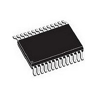
L6470HTR STMicroelectronics, L6470HTR Datasheet - Page 24

L6470HTR
Manufacturer Part Number
L6470HTR
Description
IC STEPPER/DC MOTOR DVR 28HTSSOP
Manufacturer
STMicroelectronics
Specifications of L6470HTR
Lead Free Status / RoHS Status
Lead free / RoHS Compliant
Other names
497-10812-2
Available stocks
Company
Part Number
Manufacturer
Quantity
Price
Part Number:
L6470HTR
Manufacturer:
ST
Quantity:
20 000
Functional description
6.7.5
6.8
6.8.1
6.8.2
24/64
SoftHiZ command causes the motor to decelerate with programmed deceleration value until
MIN_SPEED value is reached and then forces the bridges in high impedance state (no
holding torque is present).
HardHiZ command instantly forces the bridges in high impedance state (no holding torque is
present).
Step-clock mode
In step clock mode the motor motion is defined by the step clock signal applied to STCK pin.
At each step clock rising edge, the motor is moved of one microstep in the programmed
direction and absolute position is consequently updated.
When the system is in step clock mode the SCK_MOD flag in STATUS register is raised,
SPEED register is set to zero and motor status is considered stopped whatever the STCK
signal frequency (MOT_STATUS parameter in STATUS register equal to “00”).
Internal oscillator and oscillator driver
The control logic clock can be supplied by the internal 16 MHz oscillator, an external
oscillator (crystal or ceramic resonator) or a direct clock signal.
These working modes can be selected by EXT_CLK and OSC_SEL parameters in the
CONFIG register (see
At power-up the device starts using the internal oscillator and provides a 2 MHz clock signal
on the OSCOUT pin.
Internal oscillator
In this mode the internal oscillator is activated and OSCIN is unused. If OSCOUT clock
source is enabled, OSCOUT pin provides a 2, 4, 8 or 16 MHz clock signal (according to
OSC_SEL value); otherwise it is unused (see
External clock source
Two types of external clock source can be selected: crystal/ceramic resonator or direct clock
source. Four programmable clock frequencies are available for each external clock source:
8, 16, 24 and 32 MHz.
When an external crystal/resonator is selected, OSCIN and OSCOUT pins are used to drive
the crystal/resonator (see
placed as close as possible to the pins. Refer to
value according to the external oscillator frequency.
Attention: In any case, before changing clock source configuration, a
hardware reset is mandatory.
Table
Figure
22).
Doc ID 16737 Rev 2
10). Crystal/resonator and load capacitors (C
Figure
Table 7
10).
for the choice of the load capacitor
L
) must be
L6470


