EA-QSB-103 Embedded Artists, EA-QSB-103 Datasheet - Page 19
EA-QSB-103
Manufacturer Part Number
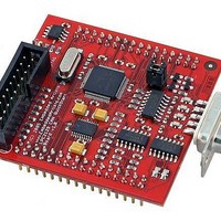
EA-QSB-103
Description
MCU, MPU & DSP Development Tools QUICKSTART PROTOTYPE BRD W/ LPC2129 CAN
Manufacturer
Embedded Artists
Specifications of EA-QSB-103
Processor To Be Evaluated
LPC2129
Data Bus Width
16 bit, 32 bit
Interface Type
RS-232, CAN, I2C, SPI, UART
Core
ARM7TDMI-S
Dimensions
55 mm x 58 mm
Maximum Operating Temperature
+ 85 C
Operating Supply Voltage
5 V
Lead Free Status / RoHS Status
Lead free / RoHS Compliant


NXP Semiconductors
Product data sheet
LPC2109_2119_2129_6
6.16.1 Features
6.16 Real-time clock
6.17 Pulse width modulator
The RTC is designed to provide a set of counters to measure time when normal or idle
operating mode is selected. The RTC has been designed to use little power, making it
suitable for battery powered systems where the CPU is not running continuously (Idle
mode).
The PWM is based on the standard Timer block and inherits all of its features, although
only the PWM function is pinned out on the LPC2109/2119/2129. The Timer is designed
to count cycles of the peripheral clock (PCLK) and optionally generate interrupts or
perform other actions when specified timer values occur, based on seven match registers.
The PWM function is also based on match register events.
The ability to separately control rising and falling edge locations allows the PWM to be
used for more applications. For instance, multi-phase motor control typically requires three
non-overlapping PWM outputs with individual control of all three pulse widths and
positions.
Two match registers can be used to provide a single edge controlled PWM output. One
match register (MR0) controls the PWM cycle rate, by resetting the count upon match.
The other match register controls the PWM edge position. Additional single edge
controlled PWM outputs require only one match register each, since the repetition rate is
the same for all PWM outputs. Multiple single edge controlled PWM outputs will all have a
rising edge at the beginning of each PWM cycle, when an MR0 match occurs.
•
•
•
•
•
•
•
•
•
Enabled by software but requires a hardware reset or a watchdog reset/interrupt to be
disabled.
Incorrect/incomplete feed sequence causes reset/interrupt if enabled.
Flag to indicate watchdog reset.
Programmable 32-bit timer with internal pre-scaler.
Selectable time period from (T
T
Measures the passage of time to maintain a calendar and clock.
Ultra low power design to support battery powered systems.
Provides Seconds, Minutes, Hours, Day of Month, Month, Year, Day of Week, and Day
of Year.
Programmable reference clock divider allows adjustment of the RTC to match various
crystal frequencies.
cy(PCLK)
4.
Rev. 06 — 10 December 2007
cy(PCLK)
256
LPC2109/2119/2129
Single-chip 16/32-bit microcontrollers
4) to (T
cy(PCLK)
2
32
© NXP B.V. 2007. All rights reserved.
4) in multiples of
19 of 44
Related parts for EA-QSB-103
Image
Part Number
Description
Manufacturer
Datasheet
Request
R

Part Number:
Description:
MCU, MPU & DSP Development Tools QUICKSTART PROTOTYPE BRD
Manufacturer:
Embedded Artists
Datasheet:

Part Number:
Description:
MCU, MPU & DSP Development Tools LPC2148 USB QUICKSTART BRD
Manufacturer:
Embedded Artists
Datasheet:

Part Number:
Description:
MCU, MPU & DSP Development Tools QUICKSTART PROTOTYPE BRD W/ LPC2106 RS232
Manufacturer:
Embedded Artists
Datasheet:

Part Number:
Description:
MCU, MPU & DSP Development Tools LPC2129 CAN QUICKSTART BRD
Manufacturer:
Embedded Artists
Datasheet:
Part Number:
Description:
MCU, MPU & DSP Development Tools QUICKSTART PROTOTYPE BRD W/ LPC2148
Manufacturer:
Embedded Artists
Datasheet:
Part Number:
Description:
MCU, MPU & DSP Development Tools LPC2106 RS232 QUICKSTART BRD
Manufacturer:
Embedded Artists
Datasheet:

Part Number:
Description:
BOARD QUICK START LPC1343
Manufacturer:
Embedded Artists
Datasheet:

Part Number:
Description:
Development Boards & Kits - ARM QUICK START BOARD LPC11U35
Manufacturer:
Embedded Artists
Datasheet:
Part Number:
Description:
KIT LPC3141 SODIMM 66X48 200POS
Manufacturer:
Embedded Artists
Datasheet:
Part Number:
Description:
KIT LPC3152 SODIMM 66X48 200POS
Manufacturer:
Embedded Artists
Datasheet:
Part Number:
Description:
BOARD OEM W/LPC2478 MCU
Manufacturer:
Embedded Artists
Datasheet:
Part Number:
Description:
KIT LPC3250 259 WITH QVGA
Manufacturer:
Embedded Artists
Datasheet: