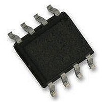
TDA8551T/N1 NXP Semiconductors, TDA8551T/N1 Datasheet - Page 8

TDA8551T/N1
Manufacturer Part Number
TDA8551T/N1
Description
AMP, AUDIO, PWR, 1.4W, MONO, 8SOIC
Manufacturer
NXP Semiconductors
Datasheet
1.TDA8551TN1112.pdf
(18 pages)
Specifications of TDA8551T/N1
Amplifier Class
AB
No. Of Channels
1
Output Power
1.4W
Supply Voltage Range
2.7V To 5.5V
Load Impedance
8ohm
Operating Temperature Range
-40°C To +85°C
Amplifier Case Style
SOIC
No. Of
RoHS Compliant
Thd + N
0.15% @ 0.5W, 8ohm, VP=5V
Rohs Compliant
Yes
Available stocks
Company
Part Number
Manufacturer
Quantity
Price
Part Number:
TDA8551T/N1
Manufacturer:
NXP/恩智浦
Quantity:
20 000
Part Number:
TDA8551T/N1,118
Manufacturer:
NXP/恩智浦
Quantity:
20 000
Company:
Part Number:
TDA8551T/N1112
Manufacturer:
NXP Semiconductors
Quantity:
1 899
Company:
Part Number:
TDA8551T/N1Ј¬118
Manufacturer:
NXP
Quantity:
2 500
NXP Semiconductors
TEST AND APPLICATION INFORMATION
Reduction of the value of capacitor C2 results in a
decrease of the SVRR performance at low frequencies
(see Fig.9).
The UP/DOWN pin can be driven by a 3-state logic output
stage (microcontroller) without extra external components.
If the UP/DOWN pin is driven by push-buttons, then it is
advised to have an RC filter between the buttons and the
UP/DOWN pin. Advised values for the RC filter are 2.2 kΩ
and 100 nF.
The volume control circuit responds to the trailing edge of
the pulse on the volume pin; connecting to V
one step (1.25 dB) higher gain; connecting to ground
results in a one step lower gain.
To avoid audible plops while switching the supply voltage
on and off pin MODE has to be connected to V
condition) during charge or discharge of the input and
SVRR capacitors.
1998 Feb 23
handbook, full pagewidth
1 W BTL audio amplifier with digital volume
control
volume
control
mute
V P
V P
UP
DOWN
standby
operating
V i
2.2 kΩ
R1
330 nF
C1
SVR
100
C5
C2
μF
IN
Fig.4 Test and application circuit.
P
4
3
100 nF
results in a
P
OPERATING
STANDBY/
CONTROL
(standby
VOLUME
MUTE/
TDA8551
1
2
MODE
UP/DOWN
8
The measured thermal resistance of the IC package is
highly dependent on the configuration and size of the
application board. Data may not be comparable between
different semiconductor manufacturers because the
application boards and test methods are not standardized
yet. In addition, the thermal performance of packages for a
specific application may be different than presented here,
because the configuration of the application boards
(copper area) may be different. NXP Semiconductors uses
FR-4 type application boards with 1 oz. copper traces with
solder coating. The measurements have been carried out
with vertical placed boards.
V P
15 kΩ
15 kΩ
6
7
GND
V P
5 kΩ
20 kΩ
MASTER
SLAVE
R
R
8
5
OUT+
OUT−
100
C3
nF
8 Ω
220
C4
μF
MGM560
Product specification
V P = 5 V
TDA8551


