194 TPI (Test Products Int), 194 Datasheet
194
Specifications of 194
194TPI
290-1424
TPI 194
TPI194
Available stocks


194 Summary of contents
Page 1
... CAPACITANCE 5µF 0.001µF (190,194) 50µF 0.01µF 500µF 0.1µF 5000µF 1µF 20mF 0.01mF CAPACITANCE 100nF 0.1nF (192) 1µF 0.001µ ...
Page 2
TABLE OF CONTENTS A. INTRODUCTION 1. Congratulations ··············· 2. Product Description ············ Declaration of Conformity B. SAFETY CONSIDERATIONS ········· C. TECHNICAL DATA 1. Features and Benefits ··········· 2. Product Applications ··········· 3. Specifications ················ D. MEASUREMENT TECHNIQUES 1. ...
Page 3
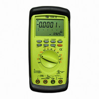
A. INTRODUCTION INTRODUCTION 1. Congratulations!! Thank you for purchasing a TPI Digital Multimeter. The Triple Display is an innovative new concept in DMM design. The unique display enables you to view more than one event at a time. This eliminates ...
Page 4
B. SAFETY CONSIDERATIONS WARNING! : Please follow manufacturers test procedures whenever possible. Do not attempt to measure unknown voltages or components until a complete understanding of the circuit is obtained. GENERAL GUIDELINES ALWAYS • Test the meter before using to ...
Page 5
C. TECHNICAL DATA 1. Features and benefits Safety Meets CE and IEC 1010 requirements. UL Listed to U.S. and Canadian Safety Standards. True RMS Needed to accurately measure non- sinusoidal AC voltage and current waveforms found on many controls and ...
Page 6
... Specifications IEC 1010 Over Voltage: (190, 192) CAT II-1000VDC, 750VAC CATIII-600V Pollution Degree 2 EC 1010 Over Voltage: (194) CATIII-1000V CATIV-600V Pollution Degree 2 ※ INSTALLATION I·II·III INSTALLATION CATEGORY(OVERVOLTAGE CATEGORY Signal level, special equipment or parts of equipment, telecommunication, electronic etc., with smaller transient overvoltages than INSTALLATION CATEGORY II. ...
Page 7
... Resolution Accuracy Overload protection Approx. 1mA 600V peak 1000V peak (Only 194) Threshold Overload protection 30digits 600V peak 1000V peak (Only 194) Resolution Accuracy 0.001uF +/-2.0% of reading, +/- 10digits 0.01uF 0.1uF 0.01mF +/-7.0% of reading, +/- 10digits Resolution Accuracy 0.1nF +/-2.0% of reading, +/- 10digits 0.001uF ...
Page 8
... HOLD Rotary Switch OFF A : 10A/600VAC 11A/1000VAC(Only 194) CAP Activates manual range Activates the Min/Max/Avg mode. Activates REL% mode. Activates the EDIT mode for the compare and relative % function. Activates Back light for the LCD(Automatically turns off after approx. 35 sec.) Activates Compare mode ...
Page 9
Selects the Inductance function Selects the Frequency function Selects the DC uA function (Push ORANGE button to activate AC uA. Selects the DC mA function (Push ORANGE button to activate AC mA.) Selects the DC A function (Push ORANGE button ...
Page 10
Step by step procedure a. Measuring DC Volts CAUTION Do not attempt to make a voltage measurement if a test lead is plugged in the input jack. Instrument damage and/or personal injury may result. WARNING! Do ...
Page 11
... CAUTION Do not attempt to make a voltage measurement if a test lead is plugged in the A or umA input jack. Instrument damage and/or personal injury may result. WARNING! Do not attempt to make a voltage measurement of more than 750V(1000V-Only 194 voltage level than is unknown. Instrument set-up: FUNCTION BLACK RED ...
Page 12
... Test leads must be connected in series with the circuit. WARNING! Do not attempt to make a current measurement of circuits with more than 600V (1000V-Only 194)present. Instrument damage and/or personal injury may result. Instrument set-up: FUNCTION BLACK ...
Page 13
Measuring Resistance WARNING! Do not attempt to make resistance measurements with circuit energized. For best results, remove the resistor completely from the circuit before attempting to measure it. NOTE: To make accurate low ohm measurements, short the ends of ...
Page 14
Continuity Buzzer WARNING! Do not attempt to make continuity measurements with circuit energized. Instrument set-up: I FUNCTION BLACK TEST LEAD COM Measurement Procedure: 1. Disconnect power to circuit to be measured. COM 2. Plug black test lead into the ...
Page 15
... FUNCTION input jack. input jack. function. WARNING! Never attempt a frequency measurement with a voltage source greater than 600V. (1000V-Only 194)Determine the voltage of any unknown frequency source before connecting the instrument in frequency source before connecting the instrument in frequency mode. BLACK RED MINIMUM ...
Page 16
Record Mode The record mode saves minimum (MIN) and maximum (MAX) values measured for a series of readings. The main part of the LCD displays the actual reading, the MAX value is constantly displayed on the lower left hand ...
Page 17
Relative % Mode The Relative % mode takes the actual reading on the main display and compares reference value programmed by the user on the right hand sub-display. The left hand sub- display will show the ...
Page 18
Push button code Push key Code RANGE RANGE AUTO/ RANGE MANUAL REC REC ON/ REC AVG/ REC OFF REL REL ON ref2/ REL OFF COMP COMP ON ref1 ref2/ COMP OFF HOLD HOLD ON/ HOLD OFF ) ref1 is the ...
Page 19
... E. ACCESSORIES Standard Accessories 9 Volt Alkaline Battery Fuse 0.5A Fuse 0.44A(Only194) Fuse 10A Fuse 11A(Only194) Test lead Rubber boot Optional Accessories Accessories Demonstration Software Deluxe Test lead set IEC 1010 Deluxe test lead kit Temperature Adaptor Current Adaptor 10/60A Current Adaptor 40/400A ...
Page 20
G. TROUBLE SHOOTING GUIDE Problem Probable Causes Does not power up • Dead or defective battery • Broken wire from battery snap to PCB Won’t display current readings • Open fuse • Open test lead • Improperly connected to circuit ...