194 TPI (Test Products Int), 194 Datasheet - Page 14
194
Manufacturer Part Number
194
Description
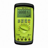
DMM AUTO-RANGE IND 600V CAT IV
Manufacturer
TPI (Test Products Int)
Series
190r
Type
Digital (DMM)r
Specifications of 194
Includes
Battery, Test Leads
Style
Handheld
Display Digits
4.75
Display Type
LCD, Bar Graph
Display Count
50000
Function
Voltage, Current, Resistance, Capacitance, Frequency
Functions, Extra
Continuity, Diode Test
Features
Auto Off, Backlight, Hold, Min/Max, RS-232 Port, Sleep
Ranging
Auto/Manual
Response
True RMS
Lead Free Status / RoHS Status
Vendor undefined / Vendor undefined
Other names
194TPI
194TPI
290-1424
TPI 194
TPI194
194TPI
290-1424
TPI 194
TPI194
Available stocks
Company
Part Number
Manufacturer
Quantity
Price
Company:

Part Number:
194-015-113-171
Manufacturer:
NorComp Inc.
Quantity:
457
Company:
Part Number:
194-015-113-531
Manufacturer:
NorComp Inc.
Quantity:
457
Company:
Part Number:
194-015-113-561
Manufacturer:
NorComp Inc.
Quantity:
457
Company:
Part Number:
194-015-113L171
Manufacturer:
NorComp Inc.
Quantity:
457
Company:
Part Number:
194-015-113L531
Manufacturer:
NorComp Inc.
Quantity:
457


25
g. Continuity Buzzer
FUNCTION
Do not attempt to make continuity measurements with
circuit energized.
I
Measurement Procedure:
1. Disconnect power to circuit to be measured.
2. Plug black test lead into the
3. Plug red test lead into the
4. Set the rotary switch to the
5. Press the yellow push button to activate the continuity
6. Connect test leads to circuit to be measured.
7. Listen for the buzzer to confirm continuity.
Instrument set-up:
buzzer.
WARNING!
BLACK TEST LEAD
COM
COM
function.
input jack.
input jack.
RED TEST LEAD
h. Measuring Capacitance
FUNCTION
All capacitance measurements are to be made on de-
energized circuit with all capacitors
Discharged only. Failure to de-energize and discharge
capacitors before attempting to measure them could result
in instrument damage and/or personal injury.
Measurement Procedure:
1. Disconnect power to circuit to be measured.
2. Remove capacitor from the circuit and discharge it.
3. Plug black test lead into the
4. Plug the red test lead into the
5. Set the rotary switch to the
6. Connect test leads to capacitor to be measured.
7. Read the capacitor value on the LCD.
WARNING!
TEST LEAD
BLACK
COM
RED
TEST LEAD
MINIMUM
READING
0.001uF
0.1nF
COM
function.
input jack.
input jack.
MAXIMUM
READING
20.00mF
120.0uF(Only 192)
26