194 TPI (Test Products Int), 194 Datasheet - Page 9
194
Manufacturer Part Number
194
Description
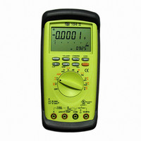
DMM AUTO-RANGE IND 600V CAT IV
Manufacturer
TPI (Test Products Int)
Series
190r
Type
Digital (DMM)r
Specifications of 194
Includes
Battery, Test Leads
Style
Handheld
Display Digits
4.75
Display Type
LCD, Bar Graph
Display Count
50000
Function
Voltage, Current, Resistance, Capacitance, Frequency
Functions, Extra
Continuity, Diode Test
Features
Auto Off, Backlight, Hold, Min/Max, RS-232 Port, Sleep
Ranging
Auto/Manual
Response
True RMS
Lead Free Status / RoHS Status
Vendor undefined / Vendor undefined
Other names
194TPI
194TPI
290-1424
TPI 194
TPI194
194TPI
290-1424
TPI 194
TPI194
Available stocks
Company
Part Number
Manufacturer
Quantity
Price
Company:

Part Number:
194-015-113-171
Manufacturer:
NorComp Inc.
Quantity:
457
Company:
Part Number:
194-015-113-531
Manufacturer:
NorComp Inc.
Quantity:
457
Company:
Part Number:
194-015-113-561
Manufacturer:
NorComp Inc.
Quantity:
457
Company:
Part Number:
194-015-113L171
Manufacturer:
NorComp Inc.
Quantity:
457
Company:
Part Number:
194-015-113L531
Manufacturer:
NorComp Inc.
Quantity:
457


15
2. Power on Options:
Adaptor
Input Jacks
V/Ohm
COM
uA/mA
A
RS-232
Disable Auto Off
Selects the DC uA function (Push ORANGE
button to activate AC uA.
Selects the DC mA function (Push
ORANGE button to activate AC mA.)
Selects the DC A function (Push ORANGE
button to activate AC A.)
Can use A254, A256, A296 and A301
(Push ORANGE button to activate AC
adaptor, and push RANGE button to
choose kind of adaptor)
Red test lead connection for all Volt, Ohm,
Diode, and Continuity measurement.
Red test lead connection for current
measurement on the AC/DC uA and AC/DC
mA.
Red test lead connection for current
measurement on the AC/DC A.
Selects the Inductance function
Selects the Frequency function
Black test lead connection for all functions.
See section on RS-232C interface
Hold down the REC button while
turning on the instrument.
Application Notes
When measuring DC Voltage of a battery, the
most accurate reading can be attained by
testing the battery under load. To accomplish
this, follow steps 1 through 4 above and the
following (with the battery in holder and device
turned on):
•
•
•
Connect the red test lead from the meter to
Connect the black test lead to the negative
Reconnect power to the circuit and read the
the
(-) terminal of the battery.
voltage on the 190.
positive (+) terminal of the battery.
16