194 TPI (Test Products Int), 194 Datasheet - Page 10
194
Manufacturer Part Number
194
Description
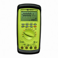
DMM AUTO-RANGE IND 600V CAT IV
Manufacturer
TPI (Test Products Int)
Series
190r
Type
Digital (DMM)r
Specifications of 194
Includes
Battery, Test Leads
Style
Handheld
Display Digits
4.75
Display Type
LCD, Bar Graph
Display Count
50000
Function
Voltage, Current, Resistance, Capacitance, Frequency
Functions, Extra
Continuity, Diode Test
Features
Auto Off, Backlight, Hold, Min/Max, RS-232 Port, Sleep
Ranging
Auto/Manual
Response
True RMS
Lead Free Status / RoHS Status
Vendor undefined / Vendor undefined
Other names
194TPI
194TPI
290-1424
TPI 194
TPI194
194TPI
290-1424
TPI 194
TPI194
Available stocks
Company
Part Number
Manufacturer
Quantity
Price
Company:

Part Number:
194-015-113-171
Manufacturer:
NorComp Inc.
Quantity:
457
Company:
Part Number:
194-015-113-531
Manufacturer:
NorComp Inc.
Quantity:
457
Company:
Part Number:
194-015-113-561
Manufacturer:
NorComp Inc.
Quantity:
457
Company:
Part Number:
194-015-113L171
Manufacturer:
NorComp Inc.
Quantity:
457
Company:
Part Number:
194-015-113L531
Manufacturer:
NorComp Inc.
Quantity:
457


17
3. Step by step procedure
a. Measuring DC Volts
Instrument set-up:
FUNCTION
CAUTION
Do not attempt to make a voltage measurement if a test
lead is plugged in the A or mA input jack. Instrument
damage and/or personal injury may result.
Do not attempt to make a voltage measurement of more
than 1000V or of voltage level that is unknown.
Measurement Procedure:
1. Disconnect power to circuit to be measured.
2. Plug black test lead into the
3. Plug red test lead into the
4. Set rotary switch to either the
5. Connect test leads to circuit to be measured.
6. Reconnect power to circuit to be measured.
7. Read the voltage on the LCD.
depending on the voltage to be measured.
WARNING!
BLACK
TEST LEAD
COM
COM
RED
TEST LEAD
VΩ
VΩ
COM
MINIMUM
READING
0.001mV
0.0001V
input jack.
input jack.
or
range,
MAXIMUM
READING
500.00mV
1000.0mV
Procedure” on page 13. Then proceed with the
following:
•
•
Connect the red test lead to the hot side of the
block and the black lead to the neutral side of the
block. Reconnect power to the block and read the
voltage on the meter. The reading should be
approximately 110V to 130V.
Disconnect power from the block and move the
red wire to ground. Reconnect power to the block
and read the voltage on the meter. Typically less
than 20V should exist from neutral to ground. If
110V or above exists, the block may be wired
incorrectly.
Application Notes
Disconnect power from the terminal
block, find the fuse or circuit breaker
that controls the block and turn it
off.
Set up the meter following the
steps under “Measurement
18