BK2534 B&K Precision, BK2534 Datasheet - Page 77
BK2534
Manufacturer Part Number
BK2534
Description
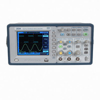
OSCOPE 60MHZ DIGITAL STORAGE
Manufacturer
B&K Precision
Type
Bench, Digitalr
Specifications of BK2534
Includes
Probes, Software, USB Cable
Bandwidth
60MHz
Channels
Dual
Display Type
LCD - Color
Features
Software Controllable, USB Port, Waveform Capture
Probe Type
PR-37A x1/x10/Ref Probes (2)
Sampling Rate (per Second)
400MSa/s
Input Impedance
1M - 19pF
Rise Time (typ)
5.83nS
Voltage - Input, Max
400Vpeak
Voltage - Supply
100 ~ 240VAC
Lead Free Status / RoHS Status
Not applicable / Not applicable


Incompatible file: This message will be displayed when the
update software is not compatible with the model type.
Load error: This message will be displayed when you fail to
load a file from the internal or external memory.
Restart to complete updating: This message will be
displayed to let you restart (power cycle) the oscilloscope
when the software update is successfully finished.
USB device is installed: This message will be displayed
when a USB device is connected and recognized by the
oscilloscope.
USB device is removed: This message will be displayed
when a USB device is removed from the oscilloscope.
Print finished: This message will be displayed when the
current waveform is printed successfully.
Print failed: This message will be displayed when the current
waveform is not printed successfully.
USB host error: This message will be displayed when the
USB host control circuit is not working correctly.
Setup finished: This message will be displayed when the
date and time are set successfully.
Setup failed: This message will be displayed when the date
and time are not set successfully.
System Message and General Problems
153
154
System Message and General Problems
General Problems
If there is no display on the screen:
If there is no waveform displayed:
If the waveform display is not stable:
Check that the power cord is connected to the
oscilloscope and to a live power source.
Check that the power switch is on.
Check that the display contrast is adjusted properly.
Contact B+K Precision if there is still no display.
Check that the oscilloscope probe id properly connected
to the BNC connector and that the probe clips make
good contact with the probe lead wires.
Check that the probe clips are securely connected to
points in the circuit under test and that the probe ground
clip is connected to the circuit ground.
Check that the circuit under test is powered on.
Press the AUTO key again.
Check that the trigger source channel is actually the
channel to which the signal is connected.
Check that the proper trigger type is selected. The video
type is only used to trigger on a video signal. The proper
trigger type is essential for a stable display.