BK2534 B&K Precision, BK2534 Datasheet - Page 9
BK2534
Manufacturer Part Number
BK2534
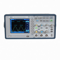
Description
OSCOPE 60MHZ DIGITAL STORAGE
Manufacturer
B&K Precision
Type
Bench, Digitalr
Specifications of BK2534
Includes
Probes, Software, USB Cable
Bandwidth
60MHz
Channels
Dual
Display Type
LCD - Color
Features
Software Controllable, USB Port, Waveform Capture
Probe Type
PR-37A x1/x10/Ref Probes (2)
Sampling Rate (per Second)
400MSa/s
Input Impedance
1M - 19pF
Rise Time (typ)
5.83nS
Voltage - Input, Max
400Vpeak
Voltage - Supply
100 ~ 240VAC
Lead Free Status / RoHS Status
Not applicable / Not applicable


2. Basic Operation
Probe Compensation
Perform this adjustment to match your probe to the input
channel. This should be done whenever you attach a passive
probe for the first time to any input channel. A poorly
compensated probe can introduce measurement errors.
1.
2.
Correctly compensated
Over compensated
Under compensated
Connect the oscilloscope probe to channel 1. Connect
the probe tip to the 3Vp-p@1kHz terminal and connect
the probe’s ground lead to the chassis ground terminal,
then press the AUTO key.
Use a nonmetallic tool to adjust the trimmer capacitor on
the probe for the flattest pulse possible. The trimmer
capacitor is located on the probe BNC connector.
Basic Operation
17
18
Basic Operation
3.
Using Autoset
The 2534 & 2540 series digital storage oscilloscopes provide
the Autoset function which sets the vertical, horizontal, and
trigger controls automatically.
Autoset function finds, turns on, and scales any channel with
a repetitive waveform that has a frequency of at least 50 Hz,
a duty cycle greater than 0.5% and an amplitude of at least
10 mV peak-to-peak. Any channels that do not meet these
requirements are turned off.
When you are using more than one channel, the Autoset
function sets the vertical controls for each channel and uses
the lowest-numbered active channel to set the horizontal and
trigger controls.
To configure the oscilloscope quickly and automatically,
press the AUTO key to display the connected signals that are
active.
To configure the oscilloscope to display multiple cycles,
press the Multi-Cycle softkey in the AUTO menu.
To configure the oscilloscope to display a single cycle, press
the Single Cycle softkey in the AUTO menu.
Connect probes to all other oscilloscope channels.
Repeat the procedure for each channel. This matches
each probe to each channel.