STPS30L45CW STMicroelectronics, STPS30L45CW Datasheet
STPS30L45CW
Specifications of STPS30L45CW
Available stocks


Related parts for STPS30L45CW


STPS30L45CW Summary of contents
Page 1
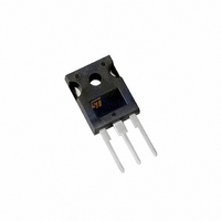
... October 2010 Low drop power Schottky rectifier PAK STPS30L45CR A1 TO-220AB STPS30L45CT TO-220FPAB STPS30L45CFP Table 1. Device summary I F(AV) V RRM T (max (max) F Doc ID 8002 Rev 4 STPS30L45C PAK STPS30L45CG TO-247 STPS30L45CW 150 °C 0.5 V 1/12 www.st.com 12 ...
Page 2
Characteristics 1 Characteristics Table 2. Absolute Ratings (limiting values, per diode) Symbol V Repetitive peak reverse voltage RRM I Forward rms current F(RMS) Average forward I F(AV) current I Surge non repetitive forward current FSM I Repetitive peak reverse current ...
Page 3
STPS30L45C Table 4. Static electrical characteristics (per diode) Symbol Parameter (1) I Reverse leakage current R (1) V Forward voltage drop F 1. Pulse test 380 µs, δ < evaluate the conduction losses use the following ...
Page 4
Characteristics Figure 5. Non repetitive surge peak forward current versus overload duration I M (A) 200 180 160 140 120 100 t(s) δ =0.5 0 1E-3 1E-2 Figure 7. Relative variation of thermal ...
Page 5
STPS30L45C Figure 11. Forward voltage drop versus forward current (maximum values, per diode) IFM(A) 200 100 Typical values Tj=150°C 10 Tj=125°C Tj=25°C VFM(V) 1 0.0 0.2 0.4 0.6 0.8 1.0 1.2 1.4 1.6 1.8 2.0 Figure 12. Thermal resistance junction ...
Page 6
Package Information 2 Package Information ● Epoxy meets UL94, V0 ● Cooling method: by conduction (C) ● Recommended torque (TO-220AB, TO-220FPAB): 0.4 to 0.6 N·m In order to meet environmental requirements, ST offers these devices in different grades of ® ...
Page 7
STPS30L45C Mounting (soldering) the I IS NOT PERMITTED. A standard through-hole mounting is mandatory. 2 Table 6. I PAK dimensions PAK metal slug (heatsink) with alloy, like a surface mount device, Ref. A ...
Page 8
Package Information Table 7. TO-220FPAB package dimensions 8/12 Ref Dia ...
Page 9
STPS30L45C 2 Table 8. D PAK package dimensions Figure 13. D PAK footprint dimensions (in millimeters) Ref ...
Page 10
Package Information Table 9. TO-247 dimensions Dimension D plus gate protrusion does not exceed 20 Resin thickness around the mounting hole is not less than 0.9 mm 10/12 ...
Page 11
... Revision history Table 11. Document revision history Date Jul-2003 13-Oct-2010 Marking Package STPS30L45CT TO-220AB 2 STPS30L45CG D PAK 2 STPS30L45CG D PAK STPS30L45CW TO-247 2 STPS30L45CR I PAK STPS30L45CFP TO-220FPAB Revision 3B Previous issue Added paragraph above 4 Table 6. Updated TO-247 dimensions in Doc ID 8002 Rev 4 Ordering Information Weight Base qty ...
Page 12
... Information in this document is provided solely in connection with ST products. STMicroelectronics NV and its subsidiaries (“ST”) reserve the right to make changes, corrections, modifications or improvements, to this document, and the products and services described herein at any time, without notice. All ST products are sold pursuant to ST’s terms and conditions of sale. ...