BYC10B-600,118 NXP Semiconductors, BYC10B-600,118 Datasheet
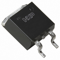
DIODE RECT 600V 10A SOT404

BYC10B-600,118

Manufacturer Part Number
BYC10B-600,118
Description
DIODE RECT 600V 10A SOT404
Manufacturer
NXP Semiconductors
Datasheet

Specifications of BYC10B-600,118

Voltage - Forward (vf) (max) @ If
2.9V @ 10A
Voltage - Dc Reverse (vr) (max)
500V
Current - Average Rectified (io)
10A
Current - Reverse Leakage @ Vr
200µA @ 600V
Diode Type
Standard
Speed
Fast Recovery =< 500ns, > 200mA (Io)
Reverse Recovery Time (trr)
55ns
Mounting Type
Surface Mount
Package / Case
D²Pak, TO-263 (2 leads + tab)
Product
Ultra Fast Recovery Rectifier
Configuration
Single
Reverse Voltage
600 V
Forward Voltage Drop
2.9 V
Recovery Time
55 ns
Forward Continuous Current
10 A
Max Surge Current
71 A
Reverse Current Ir
200 uA
Mounting Style
SMD/SMT
Maximum Operating Temperature
+ 150 C
Minimum Operating Temperature
- 40 C
Lead Free Status / RoHS Status
Lead free / RoHS Compliant
Capacitance @ Vr, F
-
Lead Free Status / Rohs Status
 Details
Other names
934054754118
BYC10B-600 /T3
BYC10B-600 /T3
Philips Semiconductors
FEATURES
• Extremely fast switching
• Low reverse recovery current
• Low thermal resistance
• Reduces switching losses in
associated MOSFET
APPLICATIONS
• Active power factor correction
• Half-bridge lighting ballasts
• Half-bridge/ full-bridge switched
mode power supplies.
The BYC10B-600 is supplied in
the SOT404 surface mounting
package.
LIMITING VALUES
Limiting values in accordance with the Absolute Maximum System (IEC 134).
THERMAL RESISTANCES
1 it is not possible to make connection to pin 2 of the SOT404 package
March 2001
Rectifier diode
ultrafast, low switching loss
SYMBOL PARAMETER
V
V
V
I
I
I
T
T
SYMBOL PARAMETER
R
R
F(AV)
FRM
FSM
stg
j
RRM
RWM
R
th j-mb
th j-a
Peak repetitive reverse voltage
Crest working reverse voltage
Continuous reverse voltage
Average forward current
Repetitive peak forward current
Non-repetitive peak forward
current.
Storage temperature
Operating junction temperature
Thermal resistance junction to
mounting base
Thermal resistance junction to
ambient
PINNING
SYMBOL
PIN
tab
1
2
3
tab
k
CONDITIONS
T
T
T
t = 10 ms
t = 8.3 ms
sinusoidal; T
with reapplied V
CONDITIONS
minimum footprint, FR4 board
mb
mb
mb
= 0.5; with reapplied V
no connection
cathode
anode
cathode
114 ˚C
78 ˚C
78 ˚C
DESCRIPTION
1
1
j
= 150˚C prior to surge
RWM(max)
3
a
RRM(max)
RRM(max)
;
;
QUICK REFERENCE DATA
SOT404
MIN.
MIN.
-
-
-40
-
-
-
-
-
-
-
-
t
rr
I
V
= 19 ns (typ)
V
F(AV)
TYP.
Product specification
R
F
50
= 600 V
1
-
= 10 A
tab
BYC10B-600
1.8 V
2
MAX.
600
600
500
150
150
3
10
20
65
71
MAX.
2
-
Rev 1.400
UNIT
UNIT
K/W
K/W
˚C
˚C
V
V
V
A
A
A
A

Related parts for BYC10B-600,118

BYC10B-600,118 Summary of contents

Page 1

... MOSFET APPLICATIONS • Active power factor correction • Half-bridge lighting ballasts • Half-bridge/ full-bridge switched mode power supplies. The BYC10B-600 is supplied in the SOT404 surface mounting package. LIMITING VALUES Limiting values in accordance with the Absolute Maximum System (IEC 134). SYMBOL PARAMETER ...

Page 2

... Vin Vin = 400 V d. 400 V d.c. OUTPUT DIODE Fig.2. Typical application, freewheeling diode in half bridge converter. Continuous conduction mode, where each transistor turns on whilst forward current is still flowing in the other bridge leg diode. 2 Product specification BYC10B-600 MIN. TYP. MAX. UNIT - 1.4 1 ...

Page 3

... F Peak reverse recovery current, Irrm (A) 100 kHz Tj = 125 400 1000 100 Fig.8. Typical peak reverse recovery current, I function of rate of change of current dI 3 Product specification BYC10B-600 Irrm ID dIF/ losses due to diode reverse recovery time VD diode reverse recovery. BYC10-600 Rate of change of current, dIF/dt (A/us) ...

Page 4

... Fig.13. Typical reverse leakage current as a function fr /dt. of reverse voltage Transient thermal impedance, Zth j-mb (K/ time 0.1 0. 0.001 1us time Fig.14. Maximum thermal impedance Product specification BYC10B-600 BYC10-600 max typ Forward voltage 25˚C and 150˚ BYC10-600 Tj = 125 C 100 100 ...

Page 5

... Plastic meets UL94 V0 at 1/8". March 2001 10.3 max 11 max 15.4 0.85 max (x2) Fig.15. SOT404 : centre pin connected to mounting base. 11.5 9.0 2.0 3.8 5.08 Fig.16. SOT404 : minimum pad sizes for surface mounting. 5 Product specification BYC10B-600 4.5 max 1.4 max 2.5 0.5 17.5 Rev 1.400 ...

Page 6

... Philips customers using or selling these products for use in such applications their own risk and agree to fully indemnify Philips for any damages resulting from such improper use or sale. March 2001 6 Product specification BYC10B-600 Rev 1.400 ...

Related keywords