STGF7NC60HD STMicroelectronics, STGF7NC60HD Datasheet
STGF7NC60HD
Specifications of STGF7NC60HD
Available stocks


Related parts for STGF7NC60HD


STGF7NC60HD Summary of contents
Page 1
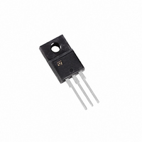
... APPLICATIONS HIGH FREQUENCY INVERTERS SMPS AND PFC IN BOTH HARD SWITCH AND RESONANT TOPOLOGIES MOTOR DRIVERS Table 2: Order Code PART NUMBER STGP7NC60HD STGF7NC60HD STGB7NC60HDT4 June 2005 STGF7NC60HD - STGB7NC60HD Very Fast PowerMESH™ IGBT Figure 1: Package (Max) I CE(sat) C @25°C @100°C < 2 < 2 < ...
Page 2
... STGP7NC60HD - STGF7NC60HD - STGB7NC60HD Table 3: Absolute Maximum ratings Symbol V Collector-Emitter Voltage (V CES V Emitter-Collector Voltage ECR V Gate-Emitter Voltage GE I Collector Current (continuous Collector Current (continuous Collector Current (pulsed Diode RMS Forward Current Total Dissipation at T TOT Derating Factor V Insulation Withstand Voltage A.C.( sec 25°C) ...
Page 3
... Eon is the turn-on losses when a typical diode is used in the test circuit in figure 2. If the IGBT is offered in a package with a co-pack diode, the co-pack diode is used as external diode. IGBTs & DIODE are at the same temperature (25°C and 125°C) (3) Turn-off losses include also the tail of the collector current. STGP7NC60HD - STGF7NC60HD - STGB7NC60HD Test Conditions V ...
Page 4
... STGP7NC60HD - STGF7NC60HD - STGB7NC60HD Table 10: Collector-Emitter Diode Symbol Parameter V Forward On-Voltage f t Reverse Recovery Time Reverse Recovery Charge Q rr Reverse Recovery Current I rrm Softness factor of the diode S t Reverse Recovery Time Reverse Recovery Charge Q rr Reverse Recovery Current I rrm Softness factor of the diode ...
Page 5
... Figure 3: Output Characteristics Figure 4: Transconductance Figure 5: Collector-Emitter On Voltage vs Col- lector Current STGP7NC60HD - STGF7NC60HD - STGB7NC60HD Figure 6: Transfer Characteristics Figure 7: Collector-Emitter On Voltage vs Tem- perature Figure 8: Normalized Gate Threshold vs Tem- perature 5/15 ...
Page 6
... STGP7NC60HD - STGF7NC60HD - STGB7NC60HD Figure 9: Normalized Breakdown Voltage vs Temperature Figure 10: Capacitance Variations Figure 11: Total Switching Losses vs Gate Re- sistance 6/15 Figure 12: Gate Charge vs Gate-Emitter Volt- age Figure 13: Total Switching Losses vs Temper- ature Figure 14: Total Switching Losses vs Collector Current ...
Page 7
... Figure 15: Thermal Impedance For TO-220/ D²PAK Figure 16: Thermal Impedance For TO-220FP STGP7NC60HD - STGF7NC60HD - STGB7NC60HD Figure 17: Turn-Off SOA Figure 18: Characteristics Emitter-Collector Diode 7/15 ...
Page 8
... STGP7NC60HD - STGF7NC60HD - STGB7NC60HD Figure 19 Frequency For a fast IGBT suitable for high frequency appli- cations, the typical collector current vs. maximum operating frequency curve is reported. That fre- quency is defined as follows MAX The maximum power dissipation is limited by maximum junction to case thermal resistance considering 125 °C- 75 °C = 50°C ...
Page 9
... Figure 20: Test Circuit for Inductive Load Switching Figure 21: Switching Waveforms STGP7NC60HD - STGF7NC60HD - STGB7NC60HD Figure 22: Gate Charge Test Circuit Figure 23: Diode Recovery Time Waveforms 9/15 ...
Page 10
... STGP7NC60HD - STGF7NC60HD - STGB7NC60HD DIM. MIN. A 4.40 b 0.61 b1 1.15 c 0.49 D 15. 2.40 e1 4.95 F 1.23 H1 6. 3.50 L20 L30 øP 3.75 Q 2.65 10/15 TO-220 MECHANICAL DATA mm. TYP MAX. MIN. 4.60 0.173 0.88 0.024 1.70 0.045 0.70 0.019 15.75 0.60 10.40 0.393 2.70 ...
Page 11
... E 0.45 F 0.75 F1 1.15 F2 1.15 G 4. 28.6 L4 9.8 L5 2 Ø 3 STGP7NC60HD - STGF7NC60HD - STGB7NC60HD MAX. MIN. 4.6 0.173 2.7 0.098 2.75 0.098 0.7 0.017 1 0.030 1.7 0.045 1.7 0.045 5.2 0.195 2.7 0.094 10.4 0.393 30.6 1.126 10.6 .0385 3.6 0.114 16 ...
Page 12
... STGP7NC60HD - STGF7NC60HD - STGB7NC60HD DIM. MIN. A 4.32 A1 0.00 b 0.71 b2 1.15 c 0.46 c2 1.22 D 8.89 D1 8.01 E 10. 13.10 L 1.30 L1 1.15 L2 1.27 L4 2.70 V2 0° 12/15 2 TO-263 (D PAK) MECHANICAL DATA mm. TYP MAX. MIN. 4.57 0.178 0.25 0.00 0.91 0.028 1.40 0.045 0.61 0.018 1.40 0.048 9 ...
Page 13
... P1 11.9 12.1 0.468 0.476 P2 1.9 2.1 0.075 0.082 R 50 1.574 T 0.25 0.35 0.0098 0.0137 W 23.7 24.3 0.933 0.956 * on sales type STGP7NC60HD - STGF7NC60HD - STGB7NC60HD REEL MECHANICAL DATA DIM. MIN 1.5 C 12.8 D 20.2 G 24.4 N 100 T BASE QTY 1000 mm inch MAX. ...
Page 14
... STGP7NC60HD - STGF7NC60HD - STGB7NC60HD Table 11: Revision History Date Revision 07-Jun-2004 4 19-Aug-2004 5 17-Sep-2004 6 09-Nov-2004 7 19-Jan-2005 8 09-Jun-2005 9 14/15 9 Description of Changes Stylesheet update. No content change Complete Version Figure 18 has been added Final datasheet Datasheet updated Modified title ...
Page 15
... Australia - Belgium - Brazil - Canada - China - Czech Republic - Finland - France - Germany - Hong Kong - India - Israel - Italy - Japan - Malaysia - Malta - Morocco - Singapore - Spain - Sweden - Switzerland - United Kingdom - United States of America STGP7NC60HD - STGF7NC60HD - STGB7NC60HD All other names are the property of their respective owners © 2005 STMicroelectronics - All Rights Reserved ...