AC7 OPTO 22, AC7 Datasheet - Page 20
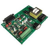
AC7
Manufacturer Part Number
AC7
Description
Computers, Interface Cards
Manufacturer
OPTO 22
Specifications of AC7
Peak Reflow Compatible (260 C)
No
Leaded Process Compatible
No
Features
RS232 To RS422 Converter
Interface
RS-422⁄485
Module Type
Adapter Card
Mounting Type
Protective Enclosure
Voltage, Supply
115 VAC ± 10 VAC @ 50⁄60 Hz
Lead Free Status / RoHS Status
Contains lead / RoHS non-compliant
Available stocks
Company
Part Number
Manufacturer
Quantity
Price

Part Number:
AC713
Manufacturer:
ALPHA
Quantity:
20 000
Part Number:
AC7201-50JC
Manufacturer:
AMD
Quantity:
20 000
Part Number:
AC744
Manufacturer:
SKYWORKS/思佳讯
Quantity:
20 000
Company:
Part Number:
AC76951
Manufacturer:
ALPHA
Quantity:
5 510
Part Number:
AC7C4096B012TCN
Manufacturer:
ALLIANCE
Quantity:
20 000


INSTALLATION (cont.)
SETTING THE AC7A/B RS-232 JUMPERS
(FIRST GROUP - NEAR THE 25-PIN RS-232 CONNECTOR)
20 AC7A/B User’s Guide
To determine whether you have a null-modem or standard cable, perform the following tests:
If you have a cable with 25-pin connectors at both ends, then test the cable for electrical continuity
between pin 2 on one end of the cable and pin 2 on the other end. These two pins are tied together on a standard
25-pin to 25-pin straight-through cable. In a 25-pin to 25-pin null-modem cable, pin 2 of one end is tied to pin 3 of
the other end.
If you have a cable with a 25-pin connector at one end, and a 9-pin on the other end, then test the cable
for electrical continuity between pin 2 on one end of the cable and pin 3 on the other end. These two pins are tied
together on a standard 25-pin to 9-pin straight-through cable. In a 25-pin to 9-pin null-modem cable, pin 2 of one end
is tied to pin 2 of the other end.
Aside from transmit, receive, and ground, other RS-232 signals are sometimes used with third-party equipment.
Some of the other signals that might be used are shown in the table below. Connections should be made if your
equipment requires them. More information on the functions of these signals is given in “Additional Technical
Information”.
* The terms “Transmit” and “Receive” for these two pins both apply from the computer’s point of view.
The six pins to the left of the jumpers labeled A through H located near the RS-232 connector on the AC7A/B
determine which pin of the RS-232 port on the AC7A/B is used for transmitting data and which pin is used for
receiving.
The AC7A/B factory default configuration uses pin 3 of the RS-232 port to receive data and pin 2 to
transmit data. Moving the jumpers to the opposite position causes pin 2 on the AC7A/B RS-232 port to receive
data, and pin 3 on the AC7A/B RS-232 port to transmit data. The jumpers may need to be moved to the other
position, depending on whether or not you are using a standard straight-through cable, or a null modem cable. The
jumpers may also need to be moved depending on what type of device is being connected to the AC7A/B. For
instance, a computer that has a DTE RS-232 port would need the jumpers in one position, whereas a modem that
has a DCE RS-232 port would need the jumpers in the opposite position. Moving the jumpers simply changes which
pin (2 or 3) on the AC7A/B receives data and which pin (2 or 3) on the AC7A/B transmits data.
Figure 3-8: 9-Pin to 25-Pin Null Modem Cable Diagram
Related parts for AC7
Image
Part Number
Description
Manufacturer
Datasheet
Request
R

Part Number:
Description:
Standard AC Input Module, 180 To 280 VAC Input Voltage Range, Voltage Input, 15 MA Output Current, 12 To 18 VDC Output Voltage, General
Manufacturer:
OPTO 22
Datasheet:

Part Number:
Description:
AC Output Module
Manufacturer:
OPTO 22
Datasheet:

Part Number:
Description:
SSR, PANEL MOUNT, 280VAC, 32VDC, 10A
Manufacturer:
OPTO 22
Datasheet:

Part Number:
Description:
SSR, PANEL MOUNT, 280VAC, 32VDC, 25A
Manufacturer:
OPTO 22
Datasheet:
Part Number:
Description:
SSR, PANEL MOUNT, 280VAC, 32VDC, 25A
Manufacturer:
OPTO 22
Datasheet:
Part Number:
Description:
SSR, PANEL MOUNT, 280VAC, 32VDC, 45A
Manufacturer:
OPTO 22
Datasheet:
Part Number:
Description:
SSR, PANEL MOUNT, 280VAC, 32VDC, 45A
Manufacturer:
OPTO 22
Datasheet:

Part Number:
Description:
Solid State Relays, Accessories
Manufacturer:
OPTO 22
Datasheet:
