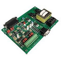
AC7 OPTO 22, AC7 Datasheet - Page 23

AC7
Manufacturer Part Number
AC7
Description
Computers, Interface Cards
Manufacturer
OPTO 22
Specifications of AC7
Peak Reflow Compatible (260 C)
No
Leaded Process Compatible
No
Features
RS232 To RS422 Converter
Interface
RS-422⁄485
Module Type
Adapter Card
Mounting Type
Protective Enclosure
Voltage, Supply
115 VAC ± 10 VAC @ 50⁄60 Hz
Lead Free Status / RoHS Status
Contains lead / RoHS non-compliant
Available stocks
Company
Part Number
Manufacturer
Quantity
Price
Part Number:
AC713
Manufacturer:
ALPHA
Quantity:
20 000
Part Number:
AC7201-50JC
Manufacturer:
AMD
Quantity:
20 000
Part Number:
AC744
Manufacturer:
SKYWORKS/思佳讯
Quantity:
20 000
Company:
Part Number:
AC76951
Manufacturer:
ALPHA
Quantity:
5 510
Part Number:
AC7C4096B012TCN
Manufacturer:
ALLIANCE
Quantity:
20 000
SETTING THE AC7A/B RS-422/485 JUMPERS
(GROUPS B AND C)
If you are using a standard, store-bought serial or null-modem RS-232 cable, and both the RS-232
and RS-422/485 devices require hardware flow control:
Install jumpers E and G on the AC7A/B, and make sure the RTS ± and CTS ± lines are connected between the
AC7A and the RS-422/485 device. Remove jumpers A, B, C, D, F, and H on the AC7A/B. This should work, although
your particular equipment may require different settings.
If your particular application does not fit into any of the above categories:
The following schematic may help you design a custom configuration. The jumpers set various leads high, or guide
the signals from the RS-232 port to the appropriate pins on the RS-422/485 port. You may to need to consult an
RS-232 or RS-422/485 reference book.
These two jumper groups are located above the green 9-screw-terminal RS-422/485 connector. Group B is on the
left, and group C is on the right.
a. Each RS-422/485 twisted pair communication cable must be terminated at both ends of the communication
b. In addition to terminating the RS-422/485 lines, as described above, each RS-422/485 twisted pair should
link only. This can be done by installing jumpers B2 (for TO or Transmit) and B4 (for FO or receive) on the
AC7A/B end. The other end of the RS-422/485 cable should be terminated with a 220 Ohm resistor
installed between the + and - terminals of each line.
also be biased at one end only. Biasing is done with pull up and pull down resistors. This can be done with
jumpers B1 and B3 (for TO or transmit) and B5 and B6 (for FO or receive) on the AC7A/B end. The purpose
of biasing is to hold the communication lines at a known intermediate voltage state when the lines are not
being driven to a high or low state by one of the devices on the communication line.
Figure 3-11: AC7A/B Jumpers A through H Schematic
AC7A/B User’s Guide 23
INSTALLATION (cont.)


