AC7 OPTO 22, AC7 Datasheet - Page 31
AC7
Manufacturer Part Number
AC7
Description
Computers, Interface Cards
Manufacturer
OPTO 22
Specifications of AC7
Peak Reflow Compatible (260 C)
No
Leaded Process Compatible
No
Features
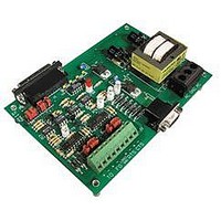
RS232 To RS422 Converter
Interface
RS-422⁄485
Module Type
Adapter Card
Mounting Type
Protective Enclosure
Voltage, Supply
115 VAC ± 10 VAC @ 50⁄60 Hz
Lead Free Status / RoHS Status
Contains lead / RoHS non-compliant
Available stocks
Company
Part Number
Manufacturer
Quantity
Price

Part Number:
AC713
Manufacturer:
ALPHA
Quantity:
20 000
Part Number:
AC7201-50JC
Manufacturer:
AMD
Quantity:
20 000
Part Number:
AC744
Manufacturer:
SKYWORKS/思佳讯
Quantity:
20 000
Company:
Part Number:
AC76951
Manufacturer:
ALPHA
Quantity:
5 510
Part Number:
AC7C4096B012TCN
Manufacturer:
ALLIANCE
Quantity:
20 000


Setup
Although this issue can be addressed using a 4-wire RS-485 wiring system, the easiest, simplest way to address this
issue is to setup each of the AC7A/Bs for 2-wire RS-485 mode, described in the previous section. However, the
discussion and diagrams of 2-wire RS-485 mode assumes there will only be one AC7A/B on the link. When using
multiple AC7A/Bs on one link, biasing and termination jumpers will need to be set differently.
Biasing
Be sure to apply biasing at only one location on the RS-485 link. When the AC7A/B is configured for 2-wire
RS-485 mode, biasing is applied by installing the B1 and B3 jumpers. These jumpers should only be installed on one
AC7A/B on the link; they should be removed for all other AC7A/Bs on the link.
Termination
Be sure to apply termination at both ends of the RS-485 link. When the AC7A/B is configured for 2-wire RS-485
mode, termination is applied by installing the B2 jumper.This jumper should be removed for all other AC7A/Bs on
the link (i.e., all AC7A/Bs that are not at the physical ends of the RS-485 link).
Wiring and Related Jumpers
When the AC7A/B is configured for 2-wire RS-485 mode, the transmitter (TO terminals) and receiver (FO terminals)
are connected together (see the wiring diagram in the previous section). Because of this, jumpers B4, B5, and B6
should be removed on all AC7A/Bs.
Additional Jumpers
In addition, since the RTS and CTS pairs are not used on the RS-422/485 side of the AC7A/B, it is best to install
jumpers C2, C4, C5, and C6 to prevent spurious LED activity.
AC7A/B User’s Guide 31
Related parts for AC7
Image
Part Number
Description
Manufacturer
Datasheet
Request
R

Part Number:
Description:
Standard AC Input Module, 180 To 280 VAC Input Voltage Range, Voltage Input, 15 MA Output Current, 12 To 18 VDC Output Voltage, General
Manufacturer:
OPTO 22
Datasheet:

Part Number:
Description:
AC Output Module
Manufacturer:
OPTO 22
Datasheet:

Part Number:
Description:
SSR, PANEL MOUNT, 280VAC, 32VDC, 10A
Manufacturer:
OPTO 22
Datasheet:

Part Number:
Description:
SSR, PANEL MOUNT, 280VAC, 32VDC, 25A
Manufacturer:
OPTO 22
Datasheet:
Part Number:
Description:
SSR, PANEL MOUNT, 280VAC, 32VDC, 25A
Manufacturer:
OPTO 22
Datasheet:
Part Number:
Description:
SSR, PANEL MOUNT, 280VAC, 32VDC, 45A
Manufacturer:
OPTO 22
Datasheet:
Part Number:
Description:
SSR, PANEL MOUNT, 280VAC, 32VDC, 45A
Manufacturer:
OPTO 22
Datasheet:

Part Number:
Description:
Solid State Relays, Accessories
Manufacturer:
OPTO 22
Datasheet:
