AC7 OPTO 22, AC7 Datasheet - Page 22
AC7
Manufacturer Part Number
AC7
Description
Computers, Interface Cards
Manufacturer
OPTO 22
Specifications of AC7
Peak Reflow Compatible (260 C)
No
Leaded Process Compatible
No
Features
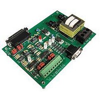
RS232 To RS422 Converter
Interface
RS-422⁄485
Module Type
Adapter Card
Mounting Type
Protective Enclosure
Voltage, Supply
115 VAC ± 10 VAC @ 50⁄60 Hz
Lead Free Status / RoHS Status
Contains lead / RoHS non-compliant
Available stocks
Company
Part Number
Manufacturer
Quantity
Price

Part Number:
AC713
Manufacturer:
ALPHA
Quantity:
20 000
Part Number:
AC7201-50JC
Manufacturer:
AMD
Quantity:
20 000
Part Number:
AC744
Manufacturer:
SKYWORKS/思佳讯
Quantity:
20 000
Company:
Part Number:
AC76951
Manufacturer:
ALPHA
Quantity:
5 510
Part Number:
AC7C4096B012TCN
Manufacturer:
ALLIANCE
Quantity:
20 000


INSTALLATION (cont.)
22 AC7A/B User’s Guide
RS-232 Handshaking Signals for Hardware Flow Control
If the RS-232 and RS-422/485 devices connected to the AC7A/B adapter card DO NOT need hardware flow control,
you may use the factory defaults for jumpers A through H and ignore this section.
If the RS-232 and/or RS-422/485 devices connected to the AC7A/B adapter card require hardware flow control,
then please read the following material.
Though the AC7A/B does have a DB-25 connector (with 25 pins) on the RS-232 side, only three pins are used for
carrying data: transmit, receive, and common (ground). The others pins are primarily used for “handshaking” or flow
control, to manage or coordinate the flow of communication. Such signals may or may not be needed by the other
devices that you are connecting to the AC7A/B adapter card. They are not needed by the AC7A/B. You may need
to jumper various pins to make the other equipment communicates properly with the AC7A/B.
Below are several examples of different applications that require different wiring and/or jumper settings:
If you are using a three-wire (TX, RX, and GND) RS-232 cable, and the RS-232 device requires
hardware flow control, but the RS-422/485 device does not:
Such a situation can arise if you are connecting a modem to an Optomux brain board with the AC7A/B. If this is the
case, physically connect CTS to RTS on the connector of the RS-232 device. Also, jumper together DSR, DCD, and
DTR on the connector of the RS-232 device. Install jumpers A, D, E, and G on the AC7A/B. Remove jumpers B, C, F,
and H on the AC7A/B.
If you are using a three-wire (TX, RX, and GND) RS-232 cable, and the RS-232 device does not
require hardware flow control, but the RS-422/485 does:
Physically connect CTS+ to RTS+ and connect CTS- to RTS- on the connector of the RS-485 device. Also, jumper
together DSR, DCD, and DTR on the connector of the RS-232 device. Install jumpers A, D, E, and G on the AC7A/B.
Remove jumpers B, C, F, and H on the AC7A/B.
If you are using a three-wire (TX, RX, and GND) RS-232 cable, and both the RS-232 and RS-422/485
devices require hardware flow control:
First connect CTS+ to RTS+ and connect CTS- to RTS- on the connector of the RS-485 device. Also physically connect
CTS to RTS on the connector of the RS-232 device. Next, jumper together DSR, DCD, and DTR on the connector of
the RS-232 device. Install jumpers A, D, E, and G on the AC7A/B. Remove jumpers B, C, F, and H on the AC7A/B.
This should work, although your particular equipment may require different settings.
If you are using a standard, store-bought serial or null-modem RS-232 cable, and the RS-232 device
requires hardware flow control, but the RS-422/485 device does not:
Install jumpers A, B, C, D, G, and H on the AC7A/B. Remove jumpers E and F on the AC7A/B.
If you are using a standard, store-bought serial or null-modem RS-232 cable, and the RS-232 device
does not require hardware flow control, but the RS-422/485 device does:
Install jumpers A, B, F, and H on the AC7A/B, and make sure the RTS ± and CTS ± lines are connected between the
AC7A and the RS-422/485 device. Remove jumpers C, D, E, and G on the AC7A/B.
Related parts for AC7
Image
Part Number
Description
Manufacturer
Datasheet
Request
R

Part Number:
Description:
Standard AC Input Module, 180 To 280 VAC Input Voltage Range, Voltage Input, 15 MA Output Current, 12 To 18 VDC Output Voltage, General
Manufacturer:
OPTO 22
Datasheet:

Part Number:
Description:
AC Output Module
Manufacturer:
OPTO 22
Datasheet:

Part Number:
Description:
SSR, PANEL MOUNT, 280VAC, 32VDC, 10A
Manufacturer:
OPTO 22
Datasheet:

Part Number:
Description:
SSR, PANEL MOUNT, 280VAC, 32VDC, 25A
Manufacturer:
OPTO 22
Datasheet:
Part Number:
Description:
SSR, PANEL MOUNT, 280VAC, 32VDC, 25A
Manufacturer:
OPTO 22
Datasheet:
Part Number:
Description:
SSR, PANEL MOUNT, 280VAC, 32VDC, 45A
Manufacturer:
OPTO 22
Datasheet:
Part Number:
Description:
SSR, PANEL MOUNT, 280VAC, 32VDC, 45A
Manufacturer:
OPTO 22
Datasheet:

Part Number:
Description:
Solid State Relays, Accessories
Manufacturer:
OPTO 22
Datasheet:
