AC7 OPTO 22, AC7 Datasheet - Page 32
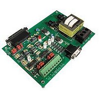
AC7
Manufacturer Part Number
AC7
Description
Computers, Interface Cards
Manufacturer
OPTO 22
Specifications of AC7
Peak Reflow Compatible (260 C)
No
Leaded Process Compatible
No
Features
RS232 To RS422 Converter
Interface
RS-422⁄485
Module Type
Adapter Card
Mounting Type
Protective Enclosure
Voltage, Supply
115 VAC ± 10 VAC @ 50⁄60 Hz
Lead Free Status / RoHS Status
Contains lead / RoHS non-compliant
Available stocks
Company
Part Number
Manufacturer
Quantity
Price

Part Number:
AC713
Manufacturer:
ALPHA
Quantity:
20 000
Part Number:
AC7201-50JC
Manufacturer:
AMD
Quantity:
20 000
Part Number:
AC744
Manufacturer:
SKYWORKS/思佳讯
Quantity:
20 000
Company:
Part Number:
AC76951
Manufacturer:
ALPHA
Quantity:
5 510
Part Number:
AC7C4096B012TCN
Manufacturer:
ALLIANCE
Quantity:
20 000


ADDITIONAL TECHNICAL INFORMATION
COMMONLY USED RS-232 SIGNALS
32 AC7A/B User’s Guide
It is possible to effectively rewire certain pins of the RS-232 connector on the AC7A/B with the group of jumpers
labeled A through H. These pins carry hardware handshaking signals which are commonly used to coordinate
communication flow.
RS-232 is a simple communication scheme that supports one device at each end of the RS-232 cable (two devices
total). In general, one device is designated DTE (data terminal equipment) and the other is designated DCE (data
communication equipment). For example, a computer is a DTE device, and a modem is the DCE device. The AC7A/B
functions as DCE when connected to a computer. For the purposes of this section, the words “computer” and
“modem” will be used in place of “DTE” and “DCE” respectively.
The standard connector used with RS-232 is the 25-pin D-shaped (DB-25) connector that is used by the AC7A/B.
A 9-pin connector (DB-9), which was first used on the IBM PC/AT, is also found on many computers. The most
commonly used RS-232 signals are given below, along with their pin assignments.
* The terms “Transmit” and “Receive” for these two pins both apply from the computer’s point of view.
RTS and DTR are both sent by the computer. DTR merely indicates that the computer is powered up and able to
communicate with the modem. RTS is sent by the computer when the computer wants to send data.
CTS, DSR, and DCD are signals sent by the modem (and therefore are inputs to the computer). DCD is high when
the modem has detected analog signals on its telephone line port that are carrying digital data. DSR is similar to
DTR — it indicates to the computer that the modem is in a state of readiness.
CTS is a response to the RTS signal. The modem realizes that the computer wants to send data when the modem’s
RTS input goes high. Then the modem sends its CTS output high when the modem is ready to receive the computer’s
data. Only when the computer senses that its CTS input is high will it start sending data.
Figure 4-5: AC7A/B Jumpers A through H Schematic
Related parts for AC7
Image
Part Number
Description
Manufacturer
Datasheet
Request
R

Part Number:
Description:
Standard AC Input Module, 180 To 280 VAC Input Voltage Range, Voltage Input, 15 MA Output Current, 12 To 18 VDC Output Voltage, General
Manufacturer:
OPTO 22
Datasheet:

Part Number:
Description:
AC Output Module
Manufacturer:
OPTO 22
Datasheet:

Part Number:
Description:
SSR, PANEL MOUNT, 280VAC, 32VDC, 10A
Manufacturer:
OPTO 22
Datasheet:

Part Number:
Description:
SSR, PANEL MOUNT, 280VAC, 32VDC, 25A
Manufacturer:
OPTO 22
Datasheet:
Part Number:
Description:
SSR, PANEL MOUNT, 280VAC, 32VDC, 25A
Manufacturer:
OPTO 22
Datasheet:
Part Number:
Description:
SSR, PANEL MOUNT, 280VAC, 32VDC, 45A
Manufacturer:
OPTO 22
Datasheet:
Part Number:
Description:
SSR, PANEL MOUNT, 280VAC, 32VDC, 45A
Manufacturer:
OPTO 22
Datasheet:

Part Number:
Description:
Solid State Relays, Accessories
Manufacturer:
OPTO 22
Datasheet:
