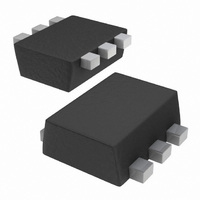
1PS66SB17,115 NXP Semiconductors, 1PS66SB17,115 Datasheet - Page 3

1PS66SB17,115
Manufacturer Part Number
1PS66SB17,115
Description
DIODE SCHOTTKY 4V 30MA SS-MINI
Manufacturer
NXP Semiconductors
Series
-r
Datasheet
1.1PS76SB17115.pdf
(8 pages)
Specifications of 1PS66SB17,115
Package / Case
SS Mini-6 (SOT-666)
Diode Type
Schottky - 3 Independent
Voltage - Peak Reverse (max)
4V
Current - Max
30mA
Capacitance @ Vr, F
0.65pF @ 0.5V, 1MHz
Product
Schottky Diodes
Peak Reverse Voltage
4 V
Forward Continuous Current
0.03 A
Configuration
Triple Parallel
Forward Voltage Drop
0.6 V @ 0.01 A
Maximum Reverse Leakage Current
0.25 uA @ 3 V
Operating Temperature Range
+ 150 C
Mounting Style
SMD/SMT
Resistance @ If, F
-
Power Dissipation (max)
-
Lead Free Status / RoHS Status
Lead free / RoHS Compliant
Power Dissipation (max)
-
Resistance @ If, F
-
Lead Free Status / Rohs Status
Lead free / RoHS Compliant
Other names
1PS66SB17 T/R
1PS66SB17 T/R
934058743115
1PS66SB17 T/R
934058743115
Philips Semiconductors
6. Thermal characteristics
7. Characteristics
9397 750 14587
Product data sheet
Table 6:
In accordance with the Absolute Maximum Rating System (IEC 60134).
Table 7:
[1]
[2]
[3]
[4]
Table 8:
T
[1]
Symbol Parameter
T
T
T
Symbol
R
Symbol
V
I
C
R
amb
j
amb
stg
F
th(j-a)
d
For Schottky barrier diodes, thermal run-away has to be considered as in some applications the reverse
power losses P
power losses P
Refer to SOD323 (SC-76) standard mounting conditions.
Refer to SOD523 (SC-79) standard mounting conditions.
Refer to SOT666 standard mounting conditions.
Pulse test: t
= 25 C unless otherwise specified.
junction temperature
ambient temperature
storage temperature
Parameter
thermal resistance from junction to
ambient;
Parameter
forward voltage
reverse current
diode
capacitance
Limiting values
Thermal characteristics
Characteristics
SOD323
SOD523
SOT666
p
R
R
300 s;
are a significant part of the total power losses. Nomograms for determining the reverse
and I
F(AV)
Rev. 06 — 4 April 2005
0.02.
rating will be available on request.
…continued
Conditions
see
V
see
R
I
I
I
V
V
F
F
F
= 3 V; see
R
R
Figure
Figure
= 0.1 mA
= 1 mA
= 10 mA
= 0 V; f = 1 MHz
= 0.5 V; f = 1 MHz
1;
3;
Conditions
Figure 2
4 V, 30 mA low C
Conditions
in free air
[1]
Min
-
-
-
-
-
-
© Koninklijke Philips Electronics N.V. 2005. All rights reserved.
Min
-
[1]
[2]
[3]
[4]
65
65
d
Typ
300
360
470
-
0.8
0.65
Min
-
-
-
Schottky barrier diode
1PSxSB17
Max
150
+150
+150
Typ
-
-
-
Max
350
450
600
250
1
-
Max
450
450
700
Unit
C
C
C
Unit
mV
mV
mV
nA
pF
pF
Unit
K/W
K/W
K/W
3 of 8


