PD57045-E STMicroelectronics, PD57045-E Datasheet
PD57045-E
Specifications of PD57045-E
Available stocks


Related parts for PD57045-E


PD57045-E Summary of contents
Page 1
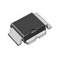
... PD57045STR-E June 2010 RF POWER transistor, LdmoST plastic family Figure 1. Gate Package PowerSO-10RF (formed lead) PowerSO-10RF (straight lead) PowerSO-10RF (formed lead) PowerSO-10RF (straight lead) Doc ID 12616 Rev 2 PD57045-E PD57045S-E PowerSO-10RF (formed lead) PowerSO-10RF (straight lead) Pin connection Source Drain Packing Tube Tube ...
Page 2
... Maximum ratings . . . . . . . . . . . . . . . . . . . . . . . . . . . . . . . . . . . . . . . . . . . . 3 1.2 Thermal data . . . . . . . . . . . . . . . . . . . . . . . . . . . . . . . . . . . . . . . . . . . . . . . 3 2 Electrical characteristics . . . . . . . . . . . . . . . . . . . . . . . . . . . . . . . . . . . . . 4 2.1 Static . . . . . . . . . . . . . . . . . . . . . . . . . . . . . . . . . . . . . . . . . . . . . . . . . . . . . 4 2.2 Dynamic . . . . . . . . . . . . . . . . . . . . . . . . . . . . . . . . . . . . . . . . . . . . . . . . . . . 4 2.3 Moisture sensitivity level . . . . . . . . . . . . . . . . . . . . . . . . . . . . . . . . . . . . . . . 4 3 Impedance . . . . . . . . . . . . . . . . . . . . . . . . . . . . . . . . . . . . . . . . . . . . . . . . . 5 4 Typical performance . . . . . . . . . . . . . . . . . . . . . . . . . . . . . . . . . . . . . . . . . 6 4.1 PD57045S Test circuit . . . . . . . . . . . . . . . . . . . . . . . . . . . . . . . . . . . . . . . . . . . . . . . . . 9 6 Common source s-parameter . . . . . . . . . . . . . . . . . . . . . . . . . . . . . . . . 12 7 Package mechanical data . . . . . . . . . . . . . . . . . . . . . . . . . . . . . . . . . . . . 14 8 Revision history . . . . . . . . . . . . . . . . . . . . . . . . . . . . . . . . . . . . . . . . . . . 19 2/20 Doc ID 12616 Rev 2 PD57045-E, PD57045S-E ...
Page 3
... PD57045-E, PD57045S-E 1 Electrical data 1.1 Maximum ratings Table 2. Absolute maximum ratings (T Symbol V (BR)DSS DISS STG 1.2 Thermal data Table 3. Thermal data Symbol R thJC CASE Parameter Drain-Source Voltage Gate-Source Voltage Drain Current Power Dissipation (@ Tc = 70°C) Max. Operating Junction Temperature Storage Temperature ...
Page 4
... MHz DS Test conditions = 250 945 MHz DQ = 250 945 MHz DQ OUT = 250 945 MHz DQ OUT = 250 945 MHz DQ OUT Test methodology J-STD-020B Doc ID 12616 Rev 2 PD57045-E, PD57045S-E Min Typ Max Unit µA 1 µA 2.0 5.0 V 0.7 0.9 V 2.0 2.7 mho 3.6 pF Min. ...
Page 5
... PD57045-E, PD57045S-E 3 Impedance Figure 2. Current conventions Table 7. Impedance data Freq. (MHz) 925 945 960 Z (Ω 2.32 . 2.92 . 2.78 Doc ID 12616 Rev 2 Impedance Z (Ω .35 1. .29 1. .83 5/20 ...
Page 6
... Figure 5. Gate-source voltage vs case temperature 1.04 1. 0.96 - Tc, CASE TEMPERATURE (°C) 6/20 Figure 2.5 Figure Doc ID 12616 Rev 2 PD57045-E, PD57045S-E Drain current vs gate voltage Vds 3.5 4 4.5 VGS, GATE-SOURCE VOLTAGE (V) Safe operating area Vds ( 100 ...
Page 7
... PD57045-E, PD57045S-E 4.1 PD57045S-E Figure 7. Output power vs input power 0.5 1 1.5 2 Pin, INPUT POWER (W) Figure 9. Power gain vs output power 17 Idq = 450 mA 16 Idq = 250 mA 15 Idq = 150 Idq = 0.1 1 Pout, OUTPUT POWER (W) Figure Pout 15 - - 250 945 MHz 10 -40 2.5 3 3.5 Figure 10 ...
Page 8
... Figure 14. Output power vs gate bias voltage 50 Pin = Pin = 2 W Pin = 1 Pin = Doc ID 12616 Rev 2 PD57045-E, PD57045S-E Pin = 1.5 W Vdd = 945 MHz 200 400 600 800 Idq, BIAS CURRENT (mA) Pin = 1.5 W Vdd = 945 MHz 0.5 1 1.5 2 2.5 3 VGS, GATE BIAS VOLTAGE (V) 1000 3 ...
Page 9
... PD57045-E, PD57045S-E 5 Test circuit Figure 15. Test circuit schematic Note: 1 Dimensions at component symbols are reference for component placement. 2 Gap between ground & transmission line = 0.056 [1.42] +0.002 [0.05] -0.000 [0.00] typ. 3 Dimensions of input and output component from edge of transmission lines. Doc ID 12616 Rev 2 ...
Page 10
... V surface mount ceramic chip capacitor 10 µF/50 V aluminum electrolytic radial lead capacitor 100 pF ATC 100B surface mount ceramic chip capacitor 220 µF/63 V aluminum electrolytic radial lead capacitor Roger, ultra lam 2000, THK 0.030”, Doc ID 12616 Rev 2 PD57045-E, PD57045S-E ε 2.55 2oz sides. ...
Page 11
... PD57045-E, PD57045S-E Figure 17. Test circuit photomaster 6.4 inches Doc ID 12616 Rev 2 Test circuit 11/20 ...
Page 12
... Doc ID 12616 Rev 2 PD57045-E, PD57045S-E < Φ < Φ 0.819 -171 -6 0.824 -175 -10 0.828 -175 -14 0.837 -176 -16 0.842 -176 -18 0.854 -176 -23 0.864 -176 -25 0 ...
Page 13
... PD57045-E, PD57045S-E Table 10. S-parameter for PD57002S-E (V Freq < Φ (MHz) 50 0.829 -161 100 0.872 -168 150 0.897 -172 200 0.910 -174 250 0.913 -175 300 0.922 -176 350 0.928 -176 400 0.934 -177 450 0.941 -178 500 0.946 -178 550 0.949 -179 600 0 ...
Page 14
... Package mechanical data 7 Package mechanical data In order to meet environmental requirements, ST offers these devices in different grades of ® ECOPACK packages, depending on their level of environmental compliance. ECOPACK specifications, grade definitions and product status are available at: www.st.com. ® ECOPACK trademark. 14/20 Doc ID 12616 Rev 2 PD57045-E, PD57045S-E ® ...
Page 15
... PD57045-E, PD57045S-E Table 11. PowerSO-10RF formed lead (Gull Wing) mechanical data Dim Note: Resin protrusions not included (max value: 0.15 mm per side) Figure 18. Package dimensions mm. Min. Typ. Max. 0 0.05 0.1 3.4 3.5 3.6 1.2 1.3 1.4 0.15 0.2 0.25 0.2 5.4 5.53 5 ...
Page 16
... Doc ID 12616 Rev 2 PD57045-E, PD57045S-E Inch Min. Typ. Max. 0.064 0.065 0.068 0.134 0.137 0.142 0.046 0.05 0.054 0.005 0.007 0.009 0.007 0.212 ...
Page 17
... PD57045-E, PD57045S-E Figure 20. Tube information Doc ID 12616 Rev 2 Package mechanical data 17/20 ...
Page 18
... Package mechanical data Figure 21. Reel information 18/20 Doc ID 12616 Rev 2 PD57045-E, PD57045S-E ...
Page 19
... PD57045-E, PD57045S-E 8 Revision history Table 13. Document revision history Date 08-Aug-2006 01-Jun-2010 Revision 1 Initial release. 2 Added: Table 6: Moisture sensitivity Doc ID 12616 Rev 2 Revision history Changes level. 19/20 ...
Page 20
... Australia - Belgium - Brazil - Canada - China - Czech Republic - Finland - France - Germany - Hong Kong - India - Israel - Italy - Japan - Malaysia - Malta - Morocco - Philippines - Singapore - Spain - Sweden - Switzerland - United Kingdom - United States of America 20/20 Please Read Carefully: © 2010 STMicroelectronics - All rights reserved STMicroelectronics group of companies www.st.com Doc ID 12616 Rev 2 PD57045-E, PD57045S-E ...