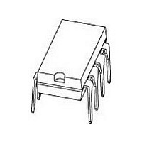
PCA82C251 NXP Semiconductors, PCA82C251 Datasheet

PCA82C251
Specifications of PCA82C251
Available stocks
Related parts for PCA82C251
PCA82C251 Summary of contents
Page 1
... DATA SHEET PCA82C251 CAN transceiver for 24 V systems Product specification Supersedes data of 1997 Mar 14 File under Integrated Circuits, IC18 INTEGRATED CIRCUITS 2000 Jan 13 ...
Page 2
... PCA82C251U bare die; 2840 2000 Jan 13 GENERAL DESCRIPTION The PCA82C251 is the interface between the CAN protocol controller and the physical bus primarily intended for applications ( Mbaud) in trucks and buses. The device provides differential transmit capability to the bus and differential receive capability to the CAN controller ...
Page 3
... Jan 13 1 PROTECTION 8 SLOPE/ Rs STANDBY 4 RECEIVER 5 REFERENCE PCA82C251 VOLTAGE Fig.1 Block diagram. handbook, halfpage 3 Product specification PCA82C251 DRIVER 7 CANH CANL 6 2 MBG613 GND TXD 1 8 GND 2 7 PCA82C251 RXD MBG612 Fig.2 Pin configuration. Rs CANH CANL V ref ...
Page 4
... Philips Semiconductors CAN transceiver for 24 V systems FUNCTIONAL DESCRIPTION The PCA82C251 is the interface between the CAN protocol controller and the physical bus primarily intended for applications Mbaud in trucks and buses. The device provides differential transmit capability to the bus and differential receive capability to the CAN controller fully compatible with the “ ...
Page 5
... V < V < 5 time CC limit; note < V < 5 time limit CC note 3 note 4 note fixed value to be used for the calculation of T th(vj-a) ) and ambient temperature (T d PARAMETER 5 Product specification PCA82C251 MIN. MAX. 0.3 +7.0 0 +36 36 +36 36 +36 36 +36 200 +200 ...
Page 6
... < unless otherwise specified note < < note 0 < < not 1 standby mode standby mode 0.97 standby mode; 0. 4 Product specification PCA82C251 MIN. TYP. MAX 275 0.3 0.3V CC 200 +30 100 600 3 +10 4.5 4.5 2.0 3.0 500 +50 200 100 200 1 ...
Page 7
... < + amb V = 4 4 < + amb see Fig see Fig < V < amb 7 Product specification PCA82C251 MIN. TYP. MAX 100 0.45V 0.55V CC CC 0.4V 0. 120 80 150 80 170 90 170 90 190 290 400 440 550 0.75V CC 10 200 0.4V 0. < UNIT ...
Page 8
... Jan 13 100 TXD 1 V ref 5 PCA82C251 RXD GND Fig.3 Test circuit for dynamic characteristics. V TXD 0 diff V RXD 0. offTXD t onTXD t onRXD Fig.4 Timing diagram for dynamic characteristics. 8 Product specification PCA82C251 CANH 7 60 100 pF CANL 6 MBG614 0 offRXD MBG615 ...
Page 9
... TXD handbook, full pagewidth V RXD TXD 2000 Jan 13 hysteresis 0.5 Fig.5 Hysteresis. t WAKE Fig.6 Timing diagram for wake up from standby. V diff t dRXDL Fig.7 Timing diagram for bus dominant to RXD low. 9 Product specification PCA82C251 MBG616 HIGH LOW 0.9 V diff ( MBG617 1 MBG618 ...
Page 10
... The waveforms of the applied transients shall be in accordance with “ISO 7637 part 1” , test pulses and 3b. handbook, full pagewidth (1) The output control register of the P8xC592 should be programmed to 1AH (push-pull operation, dominant = LOW). ( slope control is desired: R ext Fig.9 Application of the PCA82C251 CAN Transceiver. 2000 Jan 13 100 ...
Page 11
... All coordinates ( m) represent the position of the centre of each pad with respect to the bottom left-hand corner of the die (x/y = 0). handbook, full pagewidth 8 1. 2000 Jan 13 PAD PCA82C251U 1 2 2.84 mm Fig.10 Bonding pad locations. 11 Product specification PCA82C251 (1) COORDINATES x 196 1080 1567 2644 2644 1490 748 200 137 137 137 137 1644 1644 1644 1610 MGL944 ...
Page 12
... REFERENCES JEDEC EIAJ MO-001 SC-504 ( 6.48 3.60 8.25 2.54 7.62 6.20 3.05 7.80 0.26 0.14 0.32 0.10 0.30 0.24 0.12 0.31 EUROPEAN PROJECTION Product specification PCA82C251 SOT97-1 ( max. 10.0 0.254 1.15 8.3 0.39 0.01 0.045 0.33 ISSUE DATE 95-02-04 99-12-27 ...
Page 13
... REFERENCES JEDEC EIAJ MS-012 detail 1.0 0.7 1.05 0.25 0.25 0.4 0.6 0.039 0.028 0.041 0.01 0.01 0.016 0.024 EUROPEAN PROJECTION Product specification PCA82C251 SOT96 ( 0.7 0.1 0 0.028 0.004 0.012 ISSUE DATE 97-05-22 99-12-27 ...
Page 14
... Use a low voltage ( less) soldering iron applied to the flat part of the lead. Contact time must be limited to 10 seconds 300 C. When using a dedicated tool, all other leads can be soldered in one operation within seconds between 270 and 320 C. 14 Product specification PCA82C251 ...
Page 15
... Wave soldering is only suitable for SSOP and TSSOP packages with a pitch (e) equal to or larger than 0.65 mm definitely not suitable for packages with a pitch (e) equal to or smaller than 0.5 mm. 2000 Jan 13 PACKAGE suitable not suitable not suitable suitable not recommended not recommended 15 Product specification PCA82C251 SOLDERING METHOD (1) WAVE REFLOW DIPPING (2) suitable suitable (3) suitable suitable ...
Page 16
... Accordingly, Philips Semiconductors assumes no liability for device functionality or performance of the die or systems after third party sawing, handling, packing or assembly of the die the responsibility of the customer to test and qualify their application in which the die is used. 2000 Jan 13 16 Product specification PCA82C251 ...
Page 17
... Philips Semiconductors CAN transceiver for 24 V systems 2000 Jan 13 NOTES 17 Product specification PCA82C251 ...
Page 18
... Philips Semiconductors CAN transceiver for 24 V systems 2000 Jan 13 NOTES 18 Product specification PCA82C251 ...
Page 19
... Philips Semiconductors CAN transceiver for 24 V systems 2000 Jan 13 NOTES 19 Product specification PCA82C251 ...
Page 20
Philips Semiconductors – a worldwide company Argentina: see South America Australia: 3 Figtree Drive, HOMEBUSH, NSW 2140, Tel. +61 2 9704 8141, Fax. +61 2 9704 8139 Austria: Computerstr. 6, A-1101 WIEN, P.O. Box 213, Tel. + 101 ...


