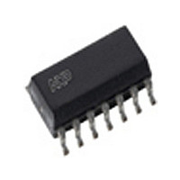
TJA1053T NXP Semiconductors, TJA1053T Datasheet - Page 10

TJA1053T
Manufacturer Part Number
TJA1053T
Description
Manufacturer
NXP Semiconductors
Datasheet
1.TJA1053T.pdf
(20 pages)
Specifications of TJA1053T
Number Of Transceivers
1
Power Down Mode
Sleep/Standby
Operating Supply Voltage (max)
5.25V
Operating Supply Voltage (typ)
5V
Operating Supply Voltage (min)
4.75V
Package Type
SO
Operating Temperature (max)
125C
Operating Temperature (min)
-40C
Operating Temperature Classification
Automotive
Mounting
Surface Mount
Pin Count
14
Lead Free Status / RoHS Status
Compliant
Available stocks
Company
Part Number
Manufacturer
Quantity
Price
Part Number:
TJA1053T
Manufacturer:
PHI
Quantity:
20 000
Company:
Part Number:
TJA1053T/N1
Manufacturer:
NXP
Quantity:
3 522
Part Number:
TJA1053T/N1
Manufacturer:
PHILIPS/飞利浦
Quantity:
20 000
Company:
Part Number:
TJA1053TD
Manufacturer:
PHILIPS
Quantity:
3 268
Company:
Part Number:
TJA1053TN1
Manufacturer:
PH
Quantity:
5 442
Philips Semiconductors
AC CHARACTERISTICS
V
ground; positive currents flow into the IC; all parameters are guaranteed over the temperature range by design, but only
100% tested at 25 C; unless otherwise specified.
2000 Dec 18
Pins RTH and RTL
R
R
V
I
I
Thermal shutdown
T
t
t
t
SYMBOL
RTLpu
RTHpd
SYMBOL
t(r-d)
t(d-r)
PD(L)
CC
jsd
oRTH
RTL
RTH
Fault-tolerant CAN transceiver
= 4.75 to 5.25 V; V
RTL to V
RTL to V
resistance
RTH to ground switch-on
resistance
RTH output voltage
RTL pull-up current
RTH pull-down current
shutdown junction temperature
CANL and CANH bus output
transition time
recessive-to-dominant
CANL and CANH bus output
transition time
dominant-to-recessive
propagation delay TXD-to-RXD
LOW
CC
BAT
PARAMETER
PARAMETER
STB
switch-on resistance
switch series
= V
CC
; V
BAT
= 6 to 27 V; T
bus failures 3, 4, 6 and 7
C1 = C2 = 3.3 nF;
R1 = 100 ;
bus failures 3, 4, 6 and 7
normal operating mode
standby mode
V
normal operating mode
I
normal operating mode,
failures 4, 6 and 7
normal operating mode,
failure 3
10% to 90%; C1 = 10 nF;
C2 = 0; R1 = 100
10% to 90%; C1 = 1 nF;
C2 = 0; R1 = 100
C1 = 100 pF; C2 = 0;
R1 = 100 ; no failures and
bus failures 1, 2 and 5
C1 = C2 = 3.3 nF;
R1 = 100 ; no failures and
bus failures 1, 2 and 5
C1 = 100 pF; C2 = 0;
R1 = 100 ;
o
I
I
I
BAT
o
o
o
= 1 mA; low power modes
< 10 mA;
< 1 mA; V
< 10 mA;
standby or sleep mode
amb
CONDITIONS
CONDITIONS
= 40 to +125 C; all voltages are defined with respect to
10
CC
8
155
0.6
0.3
MIN.
MIN.
7
15
12.5
43
0.7
75
75
165
0.85
0.4
0.75
1
0.85
1.1
TYP.
TYP.
Product specification
25
75
23
95
1.0
180
1.25
1.5
1.3
1.7
MAX.
MAX.
TJA1053
k
V
UNIT
UNIT
C
A
A
s
s
s
s
s
s


