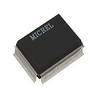
KS8993F A5 Micrel Inc, KS8993F A5 Datasheet - Page 41

KS8993F A5
Manufacturer Part Number
KS8993F A5
Description
Manufacturer
Micrel Inc
Datasheet
1.KS8993F_A5.pdf
(99 pages)
Specifications of KS8993F A5
Number Of Primary Switch Ports
3
Internal Memory Buffer Size
32
Operating Supply Voltage (typ)
1.8/2.5/3.3V
Fiber Support
Yes
Integrated Led Drivers
Yes
Phy/transceiver Interface
MII/SNI
Power Supply Type
Analog/Digital
Package Type
PQFP
Data Rate (typ)
10/100Mbps
Vlan Support
Yes
Operating Temperature (max)
70C
Operating Temperature (min)
0C
Pin Count
128
Mounting
Surface Mount
Jtag Support
No
Operating Supply Voltage (max)
1.89/3.465V
Operating Temperature Classification
Commercial
Lead Free Status / RoHS Status
Not Compliant
KS8993F
Micrel
the ingress port’s default tag. The default tags are programmed in register sets {19,20}, {35,36} and {51,52} for ports
1, 2 and 3, respectively. The KS8993F will not add tags to already tagged packets.
Tag removal is enabled by bit 1 of registers 16, 32 and 48 for ports 1, 2 and 3, respectively. Optionally, the
Px_TAGRM strap-in pins can be used to enable this feature. At the egress port, tagged packets will have their 802.1Q
VLAN Tags removed. The KS8993F will not modify untagged packets.
The CRC is recalculated for both tag insertion and tag removal.
802.1p priority field re-mapping is a QoS feature that allows the KS8993F to set the “User Priority Ceiling” at any
ingress port. If the ingress packet’s priority field has a higher priority value than the default tag’s priority field of the
ingress port, the packet’s priority field is replaced with the default tag’s priority field. The “User Priority Ceiling” is
enabled by bit 3 of registers 16, 32 and 48 for ports 1, 2 and 3, respectively.
DiffServ based priority
DiffServ based priority uses registers 96 to 103. More details are provided at the beginning of the Advanced Control
Registers section.
2.9.4 Rate Limit Support
The KS8993F supports hardware rate limiting independently on the “receive side” and on the “transmit side” on a per
port basis. Rate limiting is supported in both priority and non-priority environment. The rate limit starts from 0 kbps
and goes up to the line rate in steps of 32 kbps. The KS8993F uses “one second” as the rate limiting interval. At the
beginning of each interval, the counter is cleared to zero, and the rate limit mechanism starts to count the number of
bytes during the interval.
On the “receive side”, if the number of bytes exceeds the programmed limit, the switch will stop receiving packets on
the port until the “one second” interval expires. Flow control can be enabled to prevent packet loss. If the rate limit is
programmed greater than or equal to 128 kbps and the byte counter is 8 Kbytes below the limit, flow control will be
triggered. If the rate limit is programmed lower than 128 kbps and the byte counter is 2 Kbytes below the limit, flow
control will also be triggered.
On the “transmit side”, if the number of bytes exceeds the programmed limit, the switch will stop transmitting packets
on the port until the “one second” interval expires.
If priority is enabled, the KS8993F can be programmed to support different rate limits for high priority packets and low
priority packets.
2.10 Configuration Interface
The KS8993F can operate as both a managed switch and an unmanaged switch.
In unmanaged mode, the KS8993F is typically programmed using an EEPROM. If no EEPROM is present, the
KS8993F is configured using its default register settings. Some default register settings can be overridden via strap-in
pin options. The strap-in pins are indicated in the “KS8993F Pin Description and I/O Assignment” table in section 1.2.
August 26, 2004
Revision 1.0
- 41 -


