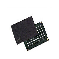
MT45V512KW16PEGA-70 WT Micron Technology Inc, MT45V512KW16PEGA-70 WT Datasheet - Page 7

MT45V512KW16PEGA-70 WT
Manufacturer Part Number
MT45V512KW16PEGA-70 WT
Description
Manufacturer
Micron Technology Inc
Datasheet
1.MT45V512KW16PEGA-70_WT.pdf
(26 pages)
Specifications of MT45V512KW16PEGA-70 WT
Operating Temperature (max)
85C
Mounting
Surface Mount
Operating Temperature Classification
Commercial
Lead Free Status / RoHS Status
Compliant
Bus Operations
Table 2:
PDF: 09005aef82f264f6/Source: 09005aef82f264aa
8mb_4mb_ap_3v_psram_p22z__2.fm - Rev. C 4/08 EN
Mode
Standby
Read
Write
No operation
PAR
DPD
Load configuration register
Bus Operations
Notes:
1. When LB# and UB# are in select mode (LOW), DQ[15:0] are affected. When LB# alone is in
2. When the device is in standby mode, control inputs (WE#, OE#), address inputs, and data
3. When WE# is active, the OE# input is internally disabled and has no effect on the I/Os.
4. The device will consume active power in this mode whenever addresses are changed.
5. V
6. DPD is enabled when configuration register bit CR[4] is “0”; otherwise, PAR is enabled.
Partial-array refresh
select mode, only DQ[7:0] are affected. When UB# alone is in the select mode, only DQ[15:8]
are affected.
inputs/outputs are internally isolated from any external influence.
current.
Deep power-down
IN
= V
Standby
Power
Active
Active
Active
CC
Idle
Q or 0V; all device balls must be static (unswitched) to achieve minimum standby
8Mb: 3.0V Core Async/Page PSRAM Memory 512K x 16
CE#
H
H
H
L
L
L
L
7
WE#
H
X
X
X
X
L
L
Micron Technology, Inc., reserves the right to change products or specifications without notice.
OE#
X
X
X
X
X
X
L
LB#/UB#
X
X
X
X
X
L
L
ZZ#
H
H
H
H
L
L
L
©2007 Micron Technology, Inc. All rights reserved.
DQ[15:0]
Data-out
Bus Operations
Data-in
High-Z
High-Z
High-Z
High-Z
X
1
Notes
1, 3, 4
1, 4
2, 5
4, 5
6
6


