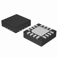
NB6L14MNG ON Semiconductor, NB6L14MNG Datasheet - Page 6

NB6L14MNG
Manufacturer Part Number
NB6L14MNG
Description
IC FANOUT BUFFER DIFF 1:4 16-QFN
Manufacturer
ON Semiconductor
Series
ECLinPS MAX™r
Type
Fanout Buffer (Distribution)r
Datasheet
1.NB6L14MNG.pdf
(10 pages)
Specifications of NB6L14MNG
Number Of Circuits
1
Ratio - Input:output
1:4
Differential - Input:output
Yes/Yes
Input
CML, LVCMOS, LVDS, LVPECL, LVTTL
Output
LVCMOS, LVPECL
Frequency - Max
3GHz
Voltage - Supply
2.375 V ~ 3.63 V
Operating Temperature
-40°C ~ 85°C
Mounting Type
Surface Mount
Package / Case
16-TFQFN Exposed Pad
Frequency-max
3GHz
Number Of Outputs
8
Max Input Freq
3000 MHz
Propagation Delay (max)
0.5 ns @ 2.375V to 3.63V
Supply Voltage (max)
3.63 V
Supply Voltage (min)
2.375 V
Maximum Operating Temperature
+ 85 C
Minimum Operating Temperature
- 40 C
Mounting Style
SMD/SMT
Supply Current
47 mA
Lead Free Status / RoHS Status
Lead free / RoHS Compliant
Other names
NB6L14MNG
NB6L14MNGOS
NB6L14MNGOS
Available stocks
Company
Part Number
Manufacturer
Quantity
Price
E5052A show additive phase noise of the NB6L14 device
at frequencies 311.04 MHz, 622.08 MHz, 1 GHz and 2 GHz
respectively at an operating voltage of 3.3 V in room
temperature. The RMS Phase Jitter contributed by the
The above phase noise plots captured using Agilent
Figure 5. Typical Phase Noise Plot at
Figure 7. Typical Phase Noise Plot at
f
carrier
f
carrier
= 311.04 MHz
= 1 GHz
http://onsemi.com
6
device (integrated between 12 kHz and 20 MHz; as shown
in the shaded region of the plot) at each of the frequencies
is 27 fs, 17 fs, 13 fs and 5 fs respectively. The input source
used for the phase noise measurements is Agilent E8663B.
Figure 6. Typical Phase Noise Plot at
Figure 8. Typical Phase Noise Plot at
f
carrier
f
carrier
= 622.08 MHz
= 2 GHz


