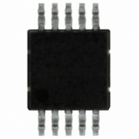
ISL1220IUZ-T Intersil, ISL1220IUZ-T Datasheet - Page 19

ISL1220IUZ-T
Manufacturer Part Number
ISL1220IUZ-T
Description
IC RTC LP BATT BACK SRAM 10MSOP
Manufacturer
Intersil
Type
Clock/Calendar/Alarmr
Datasheet
1.ISL1220IUZ-T.pdf
(20 pages)
Specifications of ISL1220IUZ-T
Memory Size
8B
Time Format
HH:MM:SS (12/24 hr)
Date Format
YY-MM-DD-dd
Interface
I²C, 2-Wire Serial
Voltage - Supply
2.7 V ~ 5.5 V
Operating Temperature
-40°C ~ 85°C
Mounting Type
Surface Mount
Package / Case
10-MSOP, Micro10™, 10-uMAX, 10-uSOP
Lead Free Status / RoHS Status
Lead free / RoHS Compliant
Other names
ISL1220IUZ-TTR
Available stocks
Company
Part Number
Manufacturer
Quantity
Price
Company:
Part Number:
ISL1220IUZ-T
Manufacturer:
Vishay
Quantity:
1 600
part in these equations, and a typical value was chosen for
example purposes. For a robust design, a margin of 30%
should be included to cover supply current and capacitance
tolerances over the results of the calculations. Even more
margin should be included if periods of very warm
temperature operation are expected.
Example 1. Calculating Backup Time Given
Voltages and Capacitor Value
In Figure 20, use C
5.0V, the voltage at V
turns off completely. The ISL1220 is specified to operate
down to V
equation is used to estimate the total backup time:
Rearranging gives:
C
voltage from fully charged to loss of operation. Note that
I
plus the leakage current of the capacitor and the diode, I
In these calculations, I
and will be ignored. If an application requires extended
operation at temperatures over 50°C, these leakages will
increase and hence reduce backup time.
Note that I
Typical Performance Curves). This allows us to make an
approximation of I
two endpoints. The typical linear equation for I
is:
Using this equation to solve for the average current given 2
voltage points gives:
dT = C
I
I = C
I
TOT
BAT
BATAVG
BAT
FIGURE 20. SUPERCAPACITOR CHARGING CIRCUIT
2.7V to 5.5V
BAT
is the total of the supply current of the ISL1220 (I
= 1.031E-7*(V
is the backup capacitance and dV is the change in
BAT
= 5.155E-8*(V
* dV/dT
BAT
BAT
* dV/I
= 1.8V. The capacitance charge/discharge
changes with V
TOT
BAT
BAT
BAT
BAT
, using a value midway between the
to solve for backup time.
LKG
= 0.47F and V
) + 1.036E-7 Amps
V
BAT2
CC
will approach 4.7V as the diode
is assumed to be extremely small
1N4148
19
+ V
GND
BAT
BAT1
almost linearly (see
V
BAT
CC
) + 1.036E-7 Amps
= 5.0V. With V
BAT
C
BAT
vs V
(EQ. 1)
(EQ. 2)
(EQ. 3)
(EQ. 4)
BAT
CC
BAT
LKG
)
=
ISL1220
.
Combining with Equation 2 gives the equation for backup
time:
where
Solving equation 4 for this example, I
Since there are 86,400 seconds in a day, this corresponds to
35.96 days. If the 30% tolerance is included for capacitor
and supply current tolerances, then worst case backup time
would be:
C
Example 2. Calculating a Capacitor Value for a
Given Backup Time
Referring to Figure 20 again, the capacitor value needs to be
calculated to give 2 months (60 days) of backup time, given
V
4.7V down to 1.8V. We will need to rearrange Equation 2 to
solve for capacitance:
Using the terms described above, this equation becomes:
where:
Solving gives:
If the 30% tolerance is included for tolerances, then worst
case cap value would be:
T
seconds
C
C
CC
BAT
BACKUP
BAT
BAT
C
V
V
I
T
T
I
I
V
V
C
C
LKG
BATAVG
LKG
BAT2
BAT1
BACKUP
BACKUP
BAT2
BAT1
BAT
BAT
BAT
= 5.0V. As in Example 1, the V
= 0.70 * 35.96 = 25.2 days
= dT*I/dV
= T
= 0 (assumed minimal)
= 0 (assumed)
= 0.47F
= 5.18 E6 * (4.387 E-7)/(2.9) = 0.784F
= 1.3 *.784 = 1.02F
= 4.7V
= 1.8V
= 4.7V
= 1.8V
BACKUP
= C
= 4.387 E-7 A (same as Example 1)
= 0.47 * (2.9) / 4.38E-7 = 3.107E6 sec
= 60 days * 86,400 sec/day = 5.18 E6 sec
BAT
* (V
* (I
BATAVG
BAT2
- V
+ I
BAT1
LKG
BAT
) / (I
)/(V
BATAVG
voltage will vary from
BATAVG
BAT2
= 4.387E-7 A
– V
+ I
BAT1
June 22, 2006
LKG
(EQ. 5)
(EQ. 7)
(EQ. 6)
FN6315.0
)
)


