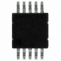
ISL1220IUZ-T Intersil, ISL1220IUZ-T Datasheet - Page 3

ISL1220IUZ-T
Manufacturer Part Number
ISL1220IUZ-T
Description
IC RTC LP BATT BACK SRAM 10MSOP
Manufacturer
Intersil
Type
Clock/Calendar/Alarmr
Datasheet
1.ISL1220IUZ-T.pdf
(20 pages)
Specifications of ISL1220IUZ-T
Memory Size
8B
Time Format
HH:MM:SS (12/24 hr)
Date Format
YY-MM-DD-dd
Interface
I²C, 2-Wire Serial
Voltage - Supply
2.7 V ~ 5.5 V
Operating Temperature
-40°C ~ 85°C
Mounting Type
Surface Mount
Package / Case
10-MSOP, Micro10™, 10-uMAX, 10-uSOP
Lead Free Status / RoHS Status
Lead free / RoHS Compliant
Other names
ISL1220IUZ-TTR
Available stocks
Company
Part Number
Manufacturer
Quantity
Price
Company:
Part Number:
ISL1220IUZ-T
Manufacturer:
Vishay
Quantity:
1 600
Serial Interface Specifications
Absolute Maximum Ratings
Voltage on V
Voltage on X1 and X2 Pins
Storage Temperature . . . . . . . . . . . . . . . . . . . . . . . .-65°C to +150°C
Lead Temperature (Soldering, 10s) . . . . . . . . . . . . . . . . . . . . . 300°C
ESD Rating (Human Body Model) . . . . . . . . . . . . . . . . . . . . . . .>2kV
ESD Rating (Machine Model . . . . . . . . . . . . . . . . . . . . . . . . . .>175V
Output Current Sink (F
CAUTION: Stresses above those listed in “Absolute Maximum Ratings” may cause permanent damage to the device. This is a stress only rating and operation of the
device at these or any other conditions above those indicated in the operational sections of this specification is not implied.
NOTE:
DC Operating Characteristics – RTC
Power-Down Timing
SERIAL INTERFACE SPECS
IRQ, F
I
SYMBOL
1. θ
LO
(respect to ground) . . . . . . . . . . . . . . . . . . . . . . . . . . -0.5V to 7.0V
(respect to ground) . . . . . . . . . . . .-0.5V to V
V
V
SYMBOL
SYMBOL
V
JA
I
V
IL
BATLKG
TRIPHYS
BATHYS
V
V
DD SR-
I
I
I
OUT
V
I
V
DD1
DD2
DD3
BAT
I
TRIP
is measured with the component mounted on a high effective thermal conductivity test board in free air. See Tech Brief TB379 for details.
BAT
I
LO
DD
OL
LI
DD
SDA and SCL Input Buffer LOW
Voltage
, V
BAT
Main Power Supply
Battery Supply Voltage
Supply Current
Supply Current with I
Supply Current (Low Power Mode)
Battery Supply Current
Battery Input Leakage
Input Leakage Current on SCL
I/O Leakage Current on SDA
V
V
V
Output Low Voltage
Output Leakage Current
V
BAT
TRIP
BAT
DD
, SCL, SDA, and IRQ, F
OUT
PARAMETER
Negative Slewrate
Mode Threshold
Hysteresis
, IRQ . . . . . . . . . . . . . . . . . . . . . . . . 3mA
Hysteresis
Temperature = -40°C to +85°C, unless otherwise stated.
PARAMETER
PARAMETER
3
-0.5V to V
2
C Active
Over the recommended operating conditions unless otherwise specified.
BAT
OUT
DD
+ 0.5 (V
+ 0.5 (V
Temperature = -40°C to +85°C, unless otherwise stated.
Pins
BAT
DD
V
V
V
V
V
V
V
V
V
V
DD
DD
DD
DD
BAT
DD
DD
DD
DD
OUT
Mode)
Mode)
TEST CONDITIONS
= 5V
= 3V
= 5V
= 5V, LPMODE = 1
= 5.5V, V
= 5V, I
= 2.7V, I
= 5.5V
= 3V
= 5.5V
ISL1220
CONDITIONS
CONDITIONS
OL
OL
BAT
= 3mA
= 1mA
Thermal Information
Thermal Resistance (Typical, Note 1)
Moisture Sensitivity (see Technical Brief TB363). . . . . . . . . . Level 2
Maximum Junction Temperature (Plastic Package). . . . . . . . . 150°C
Recommended Operating Conditions
Ambient Temperature . . . . . . . . . . . . . . . . . . . . . . . . . -40°C to 85°C
V
V
= 1.8V
DD
BAT
10 Ld MSOP Package . . . . . . . . . . . . . . . . . . . . . . .
Voltage. . . . . . . . . . . . . . . . . . . . . . . . . . . . . . . . . . 2.7V to 5.5V
Voltage . . . . . . . . . . . . . . . . . . . . . . . . . . . . . . . . . 1.8V to 5.5V
MIN
MIN
2.7
1.8
1.6
10
10
MIN
-0.3
(Note 5)
(Note 5)
TYP
TYP
400
100
100
100
1.2
1.4
2.2
40
35
50
2
(Note 5)
TYP
MAX
MAX
2.64
120
950
100
100
400
5.5
5.5
0.4
0.4
60
10
6
4
5
MAX
0.3 x
V
DD
UNITS
UNITS
V/ms
mV
mV
µA
µA
µA
µA
nA
nA
nA
nA
nA
V
V
V
V
V
UNITS
V
June 22, 2006
θ
NOTES
NOTES
JA
NOTES
2, 3
2, 3
2, 7
120
FN6315.0
2
4
(°C/W)


