1586026-5 TE Connectivity, 1586026-5 Datasheet
1586026-5
Specifications of 1586026-5
Available stocks


Related parts for 1586026-5


1586026-5 Summary of contents
Page 1
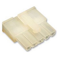
... The contacts will accept 26--16 AWG wire. When corresponding with TE Connectivity (TE) Personnel, use the terminology provided on this specification to help facilitate your inquiry for information. Basic terms and features of components are provided in Figure 1. Vertical Header ...
Page 2
REFERENCE MATERIAL 2.1. Revision Summary Updated document to corporate requirements S New logo S 2.2. Customer Assistance Reference Part Number 794954 and Product Code K924 are representative numbers of VAL--U--LOK Series Headers and Connectors. Use of these numbers will ...
Page 3
D. Chemical Exposure Do not store housings or header assemblies near any chemicals listed below, as they may cause stress corrosion cracking in the components. Alkalies Ammonia Amines Carbonates NOTE Where the above environmental conditions exist, phosphor- - bronze contacts ...
Page 4
Wire insulation shall NOT be cut or broken during the crimping operation, nor shall the insulation be crimped into the CAUTION contact wire barrel. Reasonable care should be taken by tooling operators to provide undamaged wire terminations Contact ...
Page 5
Conductor/Insulation The conductor and insulation must both be visible in the area between the insulation barrel and the wire barrel. 7. Bellmouth The front and rear bellmouths are caused by the extrusion of metal during crimping and must be ...
Page 6
Contacts Fully Inserted in Plug Housing 3.6. Strain Relief and Wire Dress If required, wires can be bundled together and supported with cable ties. Wires must not be stretched or confined in any way that would restrict the floating action ...
Page 7
Wire Bend Radius TE Engineering recommends that individual cables should be dressed to a bend radius of at least ten times the cable outside diameter. Likewise, cable bundles should be dressed to a bend radius of at least ten ...
Page 8
NUMBER OF NUMBER OF CIRCUITS Typical Vertical Header with or without Pegs and with Drain Holes A B Typical Right- - Angle Header B DIMENSION ...
Page 9
PC Board Solder Tine Holes The holes in the pc board for the solder tines must be drilled and plated through to specific dimensions. See Figure 10. Board Thickness 1.78 Max Dia of Finished Hole After Plating (Vertical 1.28 ...
Page 10
SOLDERING PROCESS SOLDERING PROCESS Wave Soldering ¯Wave Temperature C. Cleaning After soldering, removal of fluxes, residues, and activators is necessary. Consult with the supplier of the solder and flux for recommended cleaning solvents. The following is a listing of common ...
Page 11
Vertical Header Assembly 1.78 Thick PC Board PC Board 3.18. Header Assembly Spacing Care must be used to avoid interference between adjacent header assemblies and/or other components. If robotic equipment is used, space allowances will be required for the grippers. ...
Page 12
TOOLING A listing of tooling recommendations covering the full wire size range is provided in Figure 16. The listing includes hand tools for manual application of loose piece contacts, and semi--automatic and automatic machines for power assisted application of ...
Page 13
AMP LECTRIC Model “G” Terminating Machine 354500 AMP LECTRIC Model “K” Terminating Machine 565435 Heavy Duty Miniature Quick- - Change Side Feed Applicator (Typ) Rev K PC Board ...
Page 14
VISUAL AID Figure 17 shows a typical application of VAL--U--LOK Series Headers and Connectors. This illustration should be used by production personnel to ensure a correctly applied product. Applications which DO NOT appear correct should be inspected using the ...