1586026-5 TE Connectivity, 1586026-5 Datasheet - Page 12
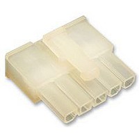
1586026-5
Manufacturer Part Number
1586026-5
Description
RECEPTACLE HOUSING, 5WAY
Manufacturer
TE Connectivity
Series
VAL-U-LOKr
Datasheet
1.1586022-4.pdf
(14 pages)
Specifications of 1586026-5
Pitch Spacing
4.2mm
No. Of Contacts
5
No. Of Rows
1
Connector Mounting
Free
Gender
Receptacle
Contact Material
Brass
Contact Plating
Tin
Colour
Clear
Rohs Compliant
Yes
Product Type
Connector
Connector Type
Housing
Termination Method To Wire/cable
Crimp
Sealed
No
Ul File Number
E28476
Csa File Number
208567
Mating Retention Type
Latching
Contact Current Rating, Max (a)
9
Operating Voltage Reference
AC
Operating Voltage (vac)
600
Profile Height (y-axis) (mm [in])
7.50 [0.295]
Number Of Positions
5
Number Of Rows
1
Centerline (mm [in])
4.20 [0.165]
Mating Retention
With
Selectively Loaded
No
Length (x-axis) (mm [in])
22.20 [0.874]
Width (z-axis) (mm [in])
19.80 [0.779]
Contact Type
Socket
Contact Design
Dual Beam
Connector Style
Receptacle
Mating Alignment
With
Mating Alignment Type
Keyed
Housing Color
Natural
Ul Flammability Rating
UL 94V-2
Rohs/elv Compliance
RoHS compliant, ELV compliant
Lead Free Solder Processes
Not relevant for lead free process
Rohs/elv Compliance History
Always was RoHS compliant
Agency/standard
UL, CSA
Ul Rating
Recognized
Circuit Identification Feature
With
Operating Temperature (°c [°f])
-40 – +105 [-40 – +221]
Applies To
Wire/Cable
Application Use
Wire-to-Board, Wire-to-Board / Wire-to-Wire, Wire-to-Wire
Contact Transmits (typical Application)
Signal (Data)
Pick And Place Cover
Without
Packaging Method
Bag
Available stocks
Company
Part Number
Manufacturer
Quantity
Price
Company:

Part Number:
1586026-5
Manufacturer:
TE Connectivity AMP Connectors
Quantity:
549


5. TOOLING
A listing of tooling recommendations covering the full wire size range is provided in Figure 16. The listing
includes hand tools for manual application of loose piece contacts, and semi--automatic and automatic
machines for power assisted application of strip form contacts. Modified designs and additional tooling
concepts may be available to meet other application requirements. For additional information, contact one of
the service groups at the bottom of page 1.
12 of 14
mm
WIRE SIZE,
WIRE SIZE,
NOTE
NOTE
0.12--0.30
0.12 0.30
0.20--0.80
0.20 0.80
S
S
S
S
S
S
[26--22]
[24--18]
1.2 [16]
i
i
2
2
Hand Crimping Tools
Hand crimping tools that accommodate the full wire size range are designed for prototype and
low--volume applications such as repair of damaged contacts.
Applicators
Applicators are designed for the full wire size range of strip--fed, precision formed contacts, and provide
for high volume, heavy duty production requirements. The applicators can be used in bench or floor
model power units.
Power Units
A power unit is an automatic or semi--automatic device used to assist in the application of a product.
Power unit includes the power source used to supply the force or power to an applicator.
Robotic Equipment
Robotic equipment for placement of the header assemblies on a pc board must have a true position
accuracy of 0.25 mm to ensure proper location and insertion of the solder tines. This includes gripper
and fixture tolerances as well as equipment repeatability. It must use the assembly datum surface to
ensure reliable header placement.
PC Board Support
A customer supplied pc board support must be used to prevent bowing of the pc board during insertion
of the headers. It should have a flat surface with holes or a channel large enough to receive the solder
tines during installation.
Extraction Tools
Extraction Tools are designed to release the contacts inside the receptacle connector without damaging
the housing or contacts. Refer to Paragraph 3.19.
[AWG]
TE Tool Engineers have designed machines for a variety of application requirements. For assistance in setting up
prototype and production line equipment, contact Tool Engineering through your local TE Representative or call the
Tooling Assistance Center number at the bottom of page 1.
Each applicator is shipped with a metal identification tag attached. DO NOT remove this tag or disregard the
information on it. Also, a packet of associated paperwork is included in each applicator shipment. This information
should be read before using the applicator; then it should be stored in a clean, dry area near the applicator for future
reference. Some changes may have to be made to the applicators to run in all related power units. Contact the Tooling
Assistance Center number at the bottom of page 1 for specific changes.
INSULATION
INSULATION
DIA RANGE
1 19 1 75
1.19--1.75
1.80--3.10
1 50 3 1
1.50--3.1
1852703--1 (408--8040)
1852703 2 (408 8040)
1852703--2 (408--8040)
1852703--3 (408--8040)
1852668--1 (408--8040)
1852668 2 (408 8040)
1852668--2 (408--8040)
1852668--3 (408--8040)
1852294--1 (408--8040)
1852294--2 (408--8040)
1852294--3 (408--8040)
APPLICATOR
Figure 16 (cont’d)
356500--1, --2 (409--5878)
356500--1, --2 (409--5878)
356500--1, --2 (409--5878)
APPLICATION TOOLING (DOCUMENT)
565435--[ ] (409--5128)
354500--[ ] (409--5842)
565435--[ ] (409--5128)
354500--[ ] (409--5842)
565435--[ ] (409--5128)
354500--[ ] (409--5842)
354500--1 (409--5842)
354500--1 (409--5842)
POWER UNIT
HAND TOOL
(408--8917)
(408--8918)
1976444--1
91387--1
91387 1
91388--1
91388 1
(N/A)
EXTRACTION TOOL
1586343--1
1586343--1
(N/A)
( / )
114- 13172
Rev K
Related parts for 1586026-5
Image
Part Number
Description
Manufacturer
Datasheet
Request
R

Part Number:
Description:
Printers THERMAL PRINTER HS-SLEEVE MARKER
Manufacturer:
TE Connectivity


Part Number:
Description:
Manufacturer:
TE Connectivity
Datasheet: