1586026-5 TE Connectivity, 1586026-5 Datasheet - Page 7
1586026-5
Manufacturer Part Number
1586026-5
Description
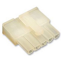
RECEPTACLE HOUSING, 5WAY
Manufacturer
TE Connectivity
Series
VAL-U-LOKr
Datasheet
1.1586022-4.pdf
(14 pages)
Specifications of 1586026-5
Pitch Spacing
4.2mm
No. Of Contacts
5
No. Of Rows
1
Connector Mounting
Free
Gender
Receptacle
Contact Material
Brass
Contact Plating
Tin
Colour
Clear
Rohs Compliant
Yes
Product Type
Connector
Connector Type
Housing
Termination Method To Wire/cable
Crimp
Sealed
No
Ul File Number
E28476
Csa File Number
208567
Mating Retention Type
Latching
Contact Current Rating, Max (a)
9
Operating Voltage Reference
AC
Operating Voltage (vac)
600
Profile Height (y-axis) (mm [in])
7.50 [0.295]
Number Of Positions
5
Number Of Rows
1
Centerline (mm [in])
4.20 [0.165]
Mating Retention
With
Selectively Loaded
No
Length (x-axis) (mm [in])
22.20 [0.874]
Width (z-axis) (mm [in])
19.80 [0.779]
Contact Type
Socket
Contact Design
Dual Beam
Connector Style
Receptacle
Mating Alignment
With
Mating Alignment Type
Keyed
Housing Color
Natural
Ul Flammability Rating
UL 94V-2
Rohs/elv Compliance
RoHS compliant, ELV compliant
Lead Free Solder Processes
Not relevant for lead free process
Rohs/elv Compliance History
Always was RoHS compliant
Agency/standard
UL, CSA
Ul Rating
Recognized
Circuit Identification Feature
With
Operating Temperature (°c [°f])
-40 – +105 [-40 – +221]
Applies To
Wire/Cable
Application Use
Wire-to-Board, Wire-to-Board / Wire-to-Wire, Wire-to-Wire
Contact Transmits (typical Application)
Signal (Data)
Pick And Place Cover
Without
Packaging Method
Bag
Available stocks
Company
Part Number
Manufacturer
Quantity
Price
Company:

Part Number:
1586026-5
Manufacturer:
TE Connectivity AMP Connectors
Quantity:
549


3.8. Wire Bend Radius
TE Engineering recommends that individual cables should be dressed to a bend radius of at least ten times the
cable outside diameter. Likewise, cable bundles should be dressed to a bend radius of at least ten times the
diameter of the bundle.
3.9. Panel Cutout
VAL--U--LOK Series Connector panel cutouts shall be as indicated in Figure 8. No mounting hardware is
required. The plug housing features flexible mounting tabs for insertion into the panel. Push the plug connector
through the panel -- in the same direction as the cutout was made -- until it snaps in place.
3.10. Header Assemblies
The pc board right--angle and vertical header assemblies are supplied with pre--installed contacts that have
right--angle or vertical solder tines. They are designed to mate with connectors that have precision formed,
crimp--type contacts inserted into 2-- through 24--position housings. The vertical header assemblies are
soldered to the pc board with or without pegs. See Figure 1.
3.11. PC Board
NOTE:
Rev K
10.00 +0.13
A. Material and Thickness
Contact the Product Information Center or the Tooling Assistance Center number listed at the bottom of
page 1 for suitability of other board materials or thicknesses.
B. Tolerance
Maximum allowable bow of the pc board shall be 0.03 mm over the length of the header assembly.
C. PC Board Layout
The mounting and contact holes in the pc board must be precisely located to ensure proper placement and
optimum performance of the header assembly. Design the pc board using the dimensions provided in
Figure 9. The layout shows the top (component) side of the board.
1. Board material will be glass epoxy (FR--4, G--10).
2. Board thickness shall be 1.78 mm max.
Panel thickness 2.00 max.
A
4.00 +0.25
(Centered +0.25 on A)
Figure 8
2.50 +0.25
(4 Places)
1.60 +0.25
5.60 +0.25 (Centered
+0.25 on 10.00 +0.13)
NUMBER OF
POSITIONS
CIRCUIT
10
12
14
16
18
20
22
24
2
4
6
8
114- 13172
10.00
14.20
18.40
22.60
26.80
31.00
35.20
39.40
43.60
47.80
52.00
+0.13
5.80
“A”
7 of 14
Related parts for 1586026-5
Image
Part Number
Description
Manufacturer
Datasheet
Request
R

Part Number:
Description:
Printers THERMAL PRINTER HS-SLEEVE MARKER
Manufacturer:
TE Connectivity


Part Number:
Description:
Manufacturer:
TE Connectivity
Datasheet: