1586026-5 TE Connectivity, 1586026-5 Datasheet - Page 4
1586026-5
Manufacturer Part Number
1586026-5
Description
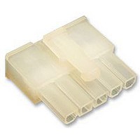
RECEPTACLE HOUSING, 5WAY
Manufacturer
TE Connectivity
Series
VAL-U-LOKr
Datasheet
1.1586022-4.pdf
(14 pages)
Specifications of 1586026-5
Pitch Spacing
4.2mm
No. Of Contacts
5
No. Of Rows
1
Connector Mounting
Free
Gender
Receptacle
Contact Material
Brass
Contact Plating
Tin
Colour
Clear
Rohs Compliant
Yes
Product Type
Connector
Connector Type
Housing
Termination Method To Wire/cable
Crimp
Sealed
No
Ul File Number
E28476
Csa File Number
208567
Mating Retention Type
Latching
Contact Current Rating, Max (a)
9
Operating Voltage Reference
AC
Operating Voltage (vac)
600
Profile Height (y-axis) (mm [in])
7.50 [0.295]
Number Of Positions
5
Number Of Rows
1
Centerline (mm [in])
4.20 [0.165]
Mating Retention
With
Selectively Loaded
No
Length (x-axis) (mm [in])
22.20 [0.874]
Width (z-axis) (mm [in])
19.80 [0.779]
Contact Type
Socket
Contact Design
Dual Beam
Connector Style
Receptacle
Mating Alignment
With
Mating Alignment Type
Keyed
Housing Color
Natural
Ul Flammability Rating
UL 94V-2
Rohs/elv Compliance
RoHS compliant, ELV compliant
Lead Free Solder Processes
Not relevant for lead free process
Rohs/elv Compliance History
Always was RoHS compliant
Agency/standard
UL, CSA
Ul Rating
Recognized
Circuit Identification Feature
With
Operating Temperature (°c [°f])
-40 – +105 [-40 – +221]
Applies To
Wire/Cable
Application Use
Wire-to-Board, Wire-to-Board / Wire-to-Wire, Wire-to-Wire
Contact Transmits (typical Application)
Signal (Data)
Pick And Place Cover
Without
Packaging Method
Bag
Available stocks
Company
Part Number
Manufacturer
Quantity
Price
Company:

Part Number:
1586026-5
Manufacturer:
TE Connectivity AMP Connectors
Quantity:
549


NOTE:
4 of 14
CAUTION
0.10 Max.
Wire Barrel
Flash
A. Contact Crimp Features
Figure 3 shows a typical contact as it should appear after crimping.
!
1. Crimp Location
For optimum crimp effectiveness, the crimp must be within the area shown and must meet the crimp
requirements provided in Figure 3.
2. Crimp Height
The crimp applied to the wire barrel portion of the contact is the most compressed area and is most
critical in ensuring optimum electrical and mechanical performance of the terminated contact. The
contact wire barrel crimp height must be within the dimension provided in Figure 2.
3. Effective Crimp Length
Effective crimp length shall be defined as that portion of the wire barrel, excluding bellmouth(s), fully
formed by the crimping tool. See Figure 3.
4. Conductor Extension
The conductor may extend beyond the wire barrel to the maximum shown in Figure 3.
5. Wire Barrel Seam
The wire barrel seam must be closed with no evidence of loose wire strands visible in the seam.
Receptacle contact shown,
but pin contact dimensions
are the same.
Wire insulation shall NOT be cut or broken during the crimping operation, nor shall the insulation be crimped into the
contact wire barrel. Reasonable care should be taken by tooling operators to provide undamaged wire terminations.
Section X- - X
Wire Barrel
Crimp Width
Wire Barrel
Crimp Height
0.40 Max. Front Bellmouth
Crimp Location
0.90 Max.
Conductor
Extension
Wire Barrel Seam Closed with No
Conductor Strands Showing
Front of
Contact
Figure 3
X
X
No Twist
Permitted
Wire
Barrel
0.00 - - 0.50
Cutoff Tab
0.30- - 0.65
Rear Bellmouth
See View A
Conductor and Insulation Must
Both be Visible in this Area
Insulation Barrel
Crimp Width
View A
114- 13172
0.10 Max.
Burr
Rev K
Related parts for 1586026-5
Image
Part Number
Description
Manufacturer
Datasheet
Request
R

Part Number:
Description:
Printers THERMAL PRINTER HS-SLEEVE MARKER
Manufacturer:
TE Connectivity


Part Number:
Description:
Manufacturer:
TE Connectivity
Datasheet: