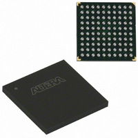
EPM570F100C4N Altera, EPM570F100C4N Datasheet - Page 51

EPM570F100C4N
Manufacturer Part Number
EPM570F100C4N
Description
IC MAX II CPLD 570 LE 100-FBGA
Manufacturer
Altera
Series
MAX® IIr
Specifications of EPM570F100C4N
Programmable Type
In System Programmable
Delay Time Tpd(1) Max
5.4ns
Voltage Supply - Internal
2.5V, 3.3V
Number Of Logic Elements/blocks
570
Number Of Macrocells
440
Number Of I /o
76
Operating Temperature
0°C ~ 85°C
Mounting Type
Surface Mount
Package / Case
100-FBGA
Voltage
2.5V, 3.3V
Memory Type
FLASH
Number Of Logic Elements/cells
570
Family Name
MAX II
# Macrocells
440
Frequency (max)
2.3148GHz
Propagation Delay Time
7ns
Number Of Logic Blocks/elements
57
# I/os (max)
76
Operating Supply Voltage (typ)
2.5/3.3V
In System Programmable
Yes
Operating Supply Voltage (min)
2.375V
Operating Supply Voltage (max)
3.6V
Operating Temp Range
0C to 85C
Operating Temperature Classification
Commercial
Mounting
Surface Mount
Pin Count
100
Package Type
FBGA
No. Of I/o's
76
Propagation Delay
7ns
Global Clock Setup Time
1.5ns
Frequency
247.5MHz
Supply Voltage Range
2.375V To 2.625V, 3V To 3.6V
Operating Temperature Range
0°C To +85°C
Rohs Compliant
Yes
Lead Free Status / RoHS Status
Lead free / RoHS Compliant
Features
-
Lead Free Status / Rohs Status
Compliant
Other names
544-1716
Available stocks
Company
Part Number
Manufacturer
Quantity
Price
Company:
Part Number:
EPM570F100C4N
Manufacturer:
ALTERA
Quantity:
12 388
Company:
Part Number:
EPM570F100C4N
Manufacturer:
ALTERA
Quantity:
325
Part Number:
EPM570F100C4N
Manufacturer:
ALTERA/阿尔特拉
Quantity:
20 000
Introduction
MAX II Hot-Socketing Specifications
Devices Can Be Driven before Power-Up
© October 2008 Altera Corporation
MII51004-2.1
1
MAX
power sequencing support. Designers can insert or remove a MAX II board in a
system during operation without undesirable effects to the system bus. The hot
socketing feature removes some of the difficulties designers face when using
components on printed circuit boards (PCBs) that contain a mixture of 3.3-, 2.5-, 1.8-,
and 1.5-V devices.
The MAX II device hot socketing feature provides:
■
■
■
This chapter contains the following sections:
■
■
MAX II devices offer all three of the features required for the hot-socketing capability
listed above without any external components or special design requirements. The
following are hot-socketing specifications:
■
■
■
Altera uses GND as reference for the hot-socketing and I/O buffers circuitry designs.
You must connect the GND between boards before connecting the V
specifications.
Signals can be driven into the MAX II device I/O pins and GCLK[3..0] pins before
or during power-up or power-down without damaging the device. MAX II devices
support any power-up or power-down sequence (V
simplifying the system-level design.
power supplies to ensure device reliability and compliance to the hot-socketing
Board or device insertion and removal
Support for any power-up sequence
Non-intrusive I/O buffers to system buses during hot insertion
“MAX II Hot-Socketing Specifications” on page 4–1
“Power-On Reset Circuitry” on page 4–5
The device can be driven before and during power-up or power-down without
any damage to the device itself.
I/O pins remain tri-stated during power-up. The device does not drive out before
or during power-up, thereby affecting other buses in operation.
Signal pins do not drive the V
to device I/O pins do not power the device V
internal paths. This is true if the V
®
II devices offer hot socketing, also known as hot plug-in or hot swap, and
4. Hot Socketing and Power-On Reset in
CCIO
or V
CCINT
CCINT
and the V
power supplies. External input signals
CCIO
CCIO
CCIO1
or V
supplies are held at GND.
, V
CCINT
CCIO2
power supplies via
MAX II Devices
, V
CCIO3
CCINT
MAX II Device Handbook
, V
and the V
CCIO4
, V
CCINT
CCIO
),


