20-101-1067 Rabbit Semiconductor, 20-101-1067 Datasheet - Page 25
20-101-1067
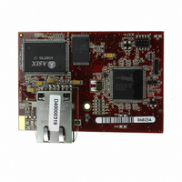
Manufacturer Part Number
20-101-1067
Description
MODULE RABBITCORE RCM3305
Manufacturer
Rabbit Semiconductor
Datasheet
1.20-101-1068.pdf
(160 pages)
Specifications of 20-101-1067
Module/board Type
MPU Core Module
Product
Microcontroller Modules
Flash
512 KBytes
Timers
10 bit
Operating Supply Voltage
3.15 to 3.45 V
Board Size
47 mm x 69 mm x 22 mm
For Use With/related Products
RCM3305
Lead Free Status / RoHS Status
Lead free / RoHS Compliant
Other names
316-1113
Available stocks
Company
Part Number
Manufacturer
Quantity
Price


3.2.1 Use of Serial Flash
3.2.1.1 Onboard Serial Flash
The following sample programs can be found in the
folder.
•
•
3.2.1.2 SF1000 Serial Flash Card
The following sample program can be found in the
•
3.2.2 Serial Communication
The following sample programs can be found in the
•
•
User’s Manual
SFLASH_INSPECT.c
serial flash chip. When the sample program starts running, it attempts to initialize a
serial flash chip on Serial Port B. Once a serial flash chip is found, the user can perform
two different commands to either print out the contents of a specified page or clear (set
to zero) all the bytes in a specified page.
SFLASH_LOG.c
the serial flash. This log can be viewed and cleared from a browser.
SERFLASHTEST.c
onstration. Install the Serial Flash card into socket J11 on the Prototyping Board. This
sample program demonstrates how to read and write from/to the Serial Flash card.
FLOWCONTROL.C
Serial Port F for CTS/RTS with serial data coming from TxE (Serial Port E) at 115,200
bps. One character at a time is received and is displayed in the
To set up the Prototyping Board, you will need to tie
TxE and RxE together on the RS-232 header at J14,
and you will also tie TxF and RxF together as shown in
the diagram.
A repeating triangular pattern should print out in the
STDIO
strate the effect of no flow control.
PARITY.C
byte values 0–127 from Serial Port E to Serial Port F. The program will switch between
generating parity or not on Serial Port E. Serial Port F will always be checking parity,
so parity errors should occur during every other sequence.
To set up the Prototyping Board, you will need to tie
TxE and RxF together on the RS-232 header at J14 as
shown in the diagram.
The Dynamic C
sequence.
window. The program will periodically switch flow control on or off to demon-
—This program demonstrates the use of parity modes by repeatedly sending
STDIO
—This program runs a simple Web server and stores a log of hits in
—This program demonstrates hardware flow control by configuring
—An optional SF1000 Serial Flash card is required to run this dem-
—This program is a handy utility for inspecting the contents of a
window will display the error
SAMPLES\RCM3300\SF1000
SAMPLES\RCM3300\SerialFlash
SAMPLES\RCM3300\SERIAL
STDIO
window.
folder.
folder.
19
Related parts for 20-101-1067
Image
Part Number
Description
Manufacturer
Datasheet
Request
R

Part Number:
Description:
COMPUTER SGL-BRD BL2500 29.4MHZ
Manufacturer:
Rabbit Semiconductor
Datasheet:

Part Number:
Description:
COMPUTER SGL-BRD BL2500 29.4MHZ
Manufacturer:
Rabbit Semiconductor
Datasheet:

Part Number:
Description:
DISPLAY GRAPHIC 12KEY PROG OP670
Manufacturer:
Rabbit Semiconductor
Datasheet:
Part Number:
Description:
DISPLAY GRAPHIC 12KEY ETH OP6700
Manufacturer:
Rabbit Semiconductor
Datasheet:

Part Number:
Description:
COMPUTER SINGLE-BOARD BL2030
Manufacturer:
Rabbit Semiconductor
Part Number:
Description:
COMPUTER SGL-BOARD ETH BL2010
Manufacturer:
Rabbit Semiconductor

Part Number:
Description:
MODULE OP6810 W/O ETH/MEM EXPANS
Manufacturer:
Rabbit Semiconductor
Datasheet:
Part Number:
Description:
COMPUTER SINGLE-BOARD BL2020
Manufacturer:
Rabbit Semiconductor
Part Number:
Description:
COMPUTER BL2010 W/FRICTION LOCK
Manufacturer:
Rabbit Semiconductor
Part Number:
Description:
COMPUTER BL2020 W/FRICTION LOCK
Manufacturer:
Rabbit Semiconductor
Part Number:
Description:
COMPUTER SGL-BRD BL2500 44.2MHZ
Manufacturer:
Rabbit Semiconductor
Datasheet:
Part Number:
Description:
COMPUTER SGL-BOARD FULL BL2000
Manufacturer:
Rabbit Semiconductor

Part Number:
Description:
COMPUTER SINGLE-BOARD BL2110
Manufacturer:
Rabbit Semiconductor

Part Number:
Description:
COMPUTER SGL-BRD 29.4MHZ BL2610
Manufacturer:
Rabbit Semiconductor
Datasheet:
Part Number:
Description:
INTERFACE OP6800 512K FLASH&SRAM
Manufacturer:
Rabbit Semiconductor
Datasheet: