20-101-1067 Rabbit Semiconductor, 20-101-1067 Datasheet - Page 87
20-101-1067
Manufacturer Part Number
20-101-1067
Description
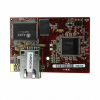
MODULE RABBITCORE RCM3305
Manufacturer
Rabbit Semiconductor
Datasheet
1.20-101-1068.pdf
(160 pages)
Specifications of 20-101-1067
Module/board Type
MPU Core Module
Product
Microcontroller Modules
Flash
512 KBytes
Timers
10 bit
Operating Supply Voltage
3.15 to 3.45 V
Board Size
47 mm x 69 mm x 22 mm
For Use With/related Products
RCM3305
Lead Free Status / RoHS Status
Lead free / RoHS Compliant
Other names
316-1113
Available stocks
Company
Part Number
Manufacturer
Quantity
Price


B.1.1 Prototyping Board Features
•
•
•
•
•
•
•
•
•
User’s Manual
Power Connection
nection to the power supply. Note that the 3-pin header is symmetrical, with both outer
pins connected to ground and the center pin connected to the raw V+ input. The cable
of the AC adapter provided with the North American version of the Development Kit
ends in a plug that connects to the power-supply jack (J1). A header plug leading to
bare leads is provided for overseas customers to connect their power supply to the 3-pin
header (J2)—the center pin of J2 is always connected to the positive terminal, and
either edge pin is negative.
Users providing their own power supply should ensure that it delivers 8–30 V DC at 1 A.
Regulated Power Supply
routed to a 5 V switching voltage regulator, then to a separate 3.3 V linear regulator.
The regulators provide stable power to the RCM3305/RCM3315 module and the Proto-
typing Board. The voltage regulators will get warm while in use.
Power LED
Board.
Core LED
plugged in correctly on the Prototyping Board and the RCM3305/RCM3315 module is
not being reset.
Relay LED
Reset Switch
RCM3305/RCM3315’s
the system.
I/O Switches and LEDs
nected to the PG0 and PG1 pins of the RCM3305/RCM3315 module and may be read
as inputs by sample applications.
Four user LEDs (DS3–DS6) are connected to alternate I/O bus pins PA0–PA3 pins of
the RCM3305/RCM3315 module via U8, and may be driven as output indicators. PE7
and PG5 control the registers in U8 as shown in the sample applications.
Prototyping Area
of through-hole components. +3.3 V, +5 V, and Ground buses run along one edge of
this area. Several areas for surface-mount devices are also available. Each SMT pad is
connected to a hole designed to accept a 30 AWG solid wire.
LCD/Keypad Module
headers LCD1JA, LCD1JB, and LCD1JC. The signals on headers LCD1JB and
LCD1JC will be available only if the LCD/keypad module is plugged in to header
LCD1JA. Appendix C provides complete information for mounting and using the
LCD/keypad module.
—The core LED lights whenever an RCM3305/RCM3315 module is
—The relay LED lights whenever the Prototyping Board relay is energized.
—The power LED lights whenever power is connected to the Prototyping
—A momentary-contact, normally open switch is connected directly to the
—A generous prototyping area has been provided for the installation
—A power-supply jack and a 3-pin header are provided for con-
—Rabbit’s LCD/keypad module may be plugged in directly to
/RESET_IN
—Two momentary-contact, normally open switches are con-
—The raw DC voltage provided at the POWER IN jack is
pin. Pressing the switch forces a hardware reset of
81
Related parts for 20-101-1067
Image
Part Number
Description
Manufacturer
Datasheet
Request
R

Part Number:
Description:
COMPUTER SGL-BRD BL2500 29.4MHZ
Manufacturer:
Rabbit Semiconductor
Datasheet:

Part Number:
Description:
COMPUTER SGL-BRD BL2500 29.4MHZ
Manufacturer:
Rabbit Semiconductor
Datasheet:

Part Number:
Description:
DISPLAY GRAPHIC 12KEY PROG OP670
Manufacturer:
Rabbit Semiconductor
Datasheet:
Part Number:
Description:
DISPLAY GRAPHIC 12KEY ETH OP6700
Manufacturer:
Rabbit Semiconductor
Datasheet:

Part Number:
Description:
COMPUTER SINGLE-BOARD BL2030
Manufacturer:
Rabbit Semiconductor
Part Number:
Description:
COMPUTER SGL-BOARD ETH BL2010
Manufacturer:
Rabbit Semiconductor

Part Number:
Description:
MODULE OP6810 W/O ETH/MEM EXPANS
Manufacturer:
Rabbit Semiconductor
Datasheet:
Part Number:
Description:
COMPUTER SINGLE-BOARD BL2020
Manufacturer:
Rabbit Semiconductor
Part Number:
Description:
COMPUTER BL2010 W/FRICTION LOCK
Manufacturer:
Rabbit Semiconductor
Part Number:
Description:
COMPUTER BL2020 W/FRICTION LOCK
Manufacturer:
Rabbit Semiconductor
Part Number:
Description:
COMPUTER SGL-BRD BL2500 44.2MHZ
Manufacturer:
Rabbit Semiconductor
Datasheet:
Part Number:
Description:
COMPUTER SGL-BOARD FULL BL2000
Manufacturer:
Rabbit Semiconductor

Part Number:
Description:
COMPUTER SINGLE-BOARD BL2110
Manufacturer:
Rabbit Semiconductor

Part Number:
Description:
COMPUTER SGL-BRD 29.4MHZ BL2610
Manufacturer:
Rabbit Semiconductor
Datasheet:
Part Number:
Description:
INTERFACE OP6800 512K FLASH&SRAM
Manufacturer:
Rabbit Semiconductor
Datasheet: