20-101-1067 Rabbit Semiconductor, 20-101-1067 Datasheet - Page 26
20-101-1067
Manufacturer Part Number
20-101-1067
Description
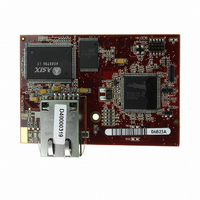
MODULE RABBITCORE RCM3305
Manufacturer
Rabbit Semiconductor
Datasheet
1.20-101-1068.pdf
(160 pages)
Specifications of 20-101-1067
Module/board Type
MPU Core Module
Product
Microcontroller Modules
Flash
512 KBytes
Timers
10 bit
Operating Supply Voltage
3.15 to 3.45 V
Board Size
47 mm x 69 mm x 22 mm
For Use With/related Products
RCM3305
Lead Free Status / RoHS Status
Lead free / RoHS Compliant
Other names
316-1113
Available stocks
Company
Part Number
Manufacturer
Quantity
Price


•
•
•
Two sample programs,
to illustrate RS-485 master/slave communication. To run these sample programs, you will
need a second Rabbit-based system with RS-485—another Rabbit single-board computer
or RabbitCore module may be used as long as you use the master or slave sample program
associated with that board.
Before running either of these sample programs on the RCM3305/RCM3315 assembly,
make sure pins 1–2 and pins 5–6 are jumpered together on header JP5 to use the RS-485
bias and termination resistors. The sample programs use Serial Port C as the RS-485 serial
port, and they use PD7 to enable/disable the RS-485 transmitter.
20
SIMPLE3WIRE.C
Lower case characters are sent by TxE, and are received by RxF. The characters are
converted to upper case and are sent out by TxF, are received by RxE, and are displayed
in the Dynamic C
To set up the Prototyping Board, you will need to tie
TxE and RxF together on the RS-232 header at J14, and
you will also tie RxE and TxF together as shown in the
diagram.
SIMPLE5WIRE.C
with flow control on Serial Port F and data flow on Serial Port E.
To set up the Prototyping Board, you will need to tie
TxE and RxE together on the RS-232 header at J14,
and you will also tie TxF and RxF together as shown in
the diagram.
Once you have compiled and run this program, you can
test flow control by disconnecting TxF from RxF while the program is running. Char-
acters will no longer appear in the
connected back to RxF.
SWITCHCHAR.C
Ports E and F. It also displays the serial data received from both ports in the
window.
To set up the Prototyping Board, you will need to tie
TxE and RxF together on the RS-232 header at J14, and
you will also tie RxE and TxF together as shown in the
diagram.
Once you have compiled and run this program, press
and release S2 and S3 on the Prototyping Board. The data sent between the serial ports
will be displayed in the
—This program transmits and then receives an ASCII string on Serial
—This program demonstrates basic RS-232 serial communication.
—This program demonstrates 5-wire RS-232 serial communication
STDIO
SIMPLE485MASTER.C
STDIO
window.
window.
STDIO
window, and will display again once TxF is
and
SIMPLE485SLAVE.C
RabbitCore RCM3305/RCM3315
, are available
STDIO
Related parts for 20-101-1067
Image
Part Number
Description
Manufacturer
Datasheet
Request
R

Part Number:
Description:
COMPUTER SGL-BRD BL2500 29.4MHZ
Manufacturer:
Rabbit Semiconductor
Datasheet:

Part Number:
Description:
COMPUTER SGL-BRD BL2500 29.4MHZ
Manufacturer:
Rabbit Semiconductor
Datasheet:

Part Number:
Description:
DISPLAY GRAPHIC 12KEY PROG OP670
Manufacturer:
Rabbit Semiconductor
Datasheet:
Part Number:
Description:
DISPLAY GRAPHIC 12KEY ETH OP6700
Manufacturer:
Rabbit Semiconductor
Datasheet:

Part Number:
Description:
COMPUTER SINGLE-BOARD BL2030
Manufacturer:
Rabbit Semiconductor
Part Number:
Description:
COMPUTER SGL-BOARD ETH BL2010
Manufacturer:
Rabbit Semiconductor

Part Number:
Description:
MODULE OP6810 W/O ETH/MEM EXPANS
Manufacturer:
Rabbit Semiconductor
Datasheet:
Part Number:
Description:
COMPUTER SINGLE-BOARD BL2020
Manufacturer:
Rabbit Semiconductor
Part Number:
Description:
COMPUTER BL2010 W/FRICTION LOCK
Manufacturer:
Rabbit Semiconductor
Part Number:
Description:
COMPUTER BL2020 W/FRICTION LOCK
Manufacturer:
Rabbit Semiconductor
Part Number:
Description:
COMPUTER SGL-BRD BL2500 44.2MHZ
Manufacturer:
Rabbit Semiconductor
Datasheet:
Part Number:
Description:
COMPUTER SGL-BOARD FULL BL2000
Manufacturer:
Rabbit Semiconductor

Part Number:
Description:
COMPUTER SINGLE-BOARD BL2110
Manufacturer:
Rabbit Semiconductor

Part Number:
Description:
COMPUTER SGL-BRD 29.4MHZ BL2610
Manufacturer:
Rabbit Semiconductor
Datasheet:
Part Number:
Description:
INTERFACE OP6800 512K FLASH&SRAM
Manufacturer:
Rabbit Semiconductor
Datasheet: