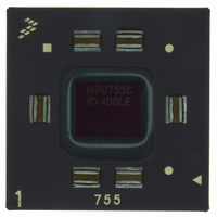
MPC755CRX400LE Freescale Semiconductor, MPC755CRX400LE Datasheet - Page 36

MPC755CRX400LE
Manufacturer Part Number
MPC755CRX400LE
Description
IC MPU 32BIT 400MHZ PPC 360-CBGA
Manufacturer
Freescale Semiconductor
Datasheet
1.MPC755BPX300LE.pdf
(56 pages)
Specifications of MPC755CRX400LE
Processor Type
MPC7xx PowerPC 32-Bit
Speed
400MHz
Voltage
2V
Mounting Type
Surface Mount
Package / Case
360-FCCBGA
Family Name
MPC7xx
Device Core
PowerPC
Device Core Size
64b
Frequency (max)
400MHz
Instruction Set Architecture
RISC
Supply Voltage 1 (typ)
2V
Operating Supply Voltage (max)
2.1V
Operating Supply Voltage (min)
1.9V
Operating Temp Range
0C to 105C
Operating Temperature Classification
Commercial
Mounting
Surface Mount
Pin Count
360
Package Type
FCCBGA
Lead Free Status / RoHS Status
Contains lead / RoHS non-compliant
Features
-
Lead Free Status / Rohs Status
Not Compliant
Available stocks
Company
Part Number
Manufacturer
Quantity
Price
Company:
Part Number:
MPC755CRX400LE
Manufacturer:
MOT
Quantity:
12 388
Company:
Part Number:
MPC755CRX400LE
Manufacturer:
Freescale Semiconductor
Quantity:
10 000
System Design Information
8
This section provides electrical and thermal design recommendations for successful application of the
MPC755.
8.1
The MPC755 PLL is configured by the PLL_CFG[0:3] signals. For a given SYSCLK (bus) frequency, the
PLL configuration signals set the internal CPU and VCO frequency of operation. These must be chosen
such that they comply with
example illustrating the core and VCO frequencies resulting from various PLL configurations and
example bus frequencies. In this example, shaded cells represent settings that, for a given SYSCLK
frequency, result in core and/or VCO frequencies that do not comply with the 400-MHz column in
36
PLL_CFG
System Design Information
0100
1000
1110
1010
0111
1011
1001
1101
0101
0010
0001
1100
0110
[0:3]
PLL Configuration
Table 16. MPC755 Microprocessor PLL Configuration Example for 400 MHz Parts
Multiplier
Bus-to-
Core
3.5x
4.5x
5.5x
6.5x
7.5x
10x
2x
3x
4x
5x
6x
7x
8x
MPC755 RISC Microprocessor Hardware Specifications, Rev. 8
Table
Multiplier
Core-to-
Example Bus-to-Core Frequency in MHz (VCO Frequency in MHz)
VCO
2x
2x
2x
2x
2x
2x
2x
2x
2x
2x
2x
2x
2x
8.
Table 16
33 MHz
(400)
(433)
(466)
(500)
(533)
(666)
Bus
200
216
233
250
266
333
—
—
—
—
—
—
—
shows the valid configurations of these signals and an
50 MHz
(400)
(450)
(500)
(550)
(600)
(650)
(700)
(750)
(800)
Bus
200
225
250
275
300
325
350
375
400
—
—
—
—
66 MHz
(400)
(466)
(533)
(600)
(666)
(733)
(800)
Bus
200
233
266
300
333
366
400
—
—
—
—
—
—
75 MHz
(450)
(525)
(600)
(675)
(750)
Bus
225
263
300
338
375
—
—
—
—
—
—
—
—
80 MHz
(480)
(560)
(640)
(720)
(800)
Bus
Freescale Semiconductor
240
280
320
360
400
—
—
—
—
—
—
—
—
100 MHz
(400)
(600)
(700)
(800)
Bus
200
300
350
400
—
—
—
—
—
—
—
—
—
Table
8.


