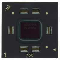
MPC755CRX400LE Freescale Semiconductor, MPC755CRX400LE Datasheet - Page 42

MPC755CRX400LE
Manufacturer Part Number
MPC755CRX400LE
Description
IC MPU 32BIT 400MHZ PPC 360-CBGA
Manufacturer
Freescale Semiconductor
Datasheet
1.MPC755BPX300LE.pdf
(56 pages)
Specifications of MPC755CRX400LE
Processor Type
MPC7xx PowerPC 32-Bit
Speed
400MHz
Voltage
2V
Mounting Type
Surface Mount
Package / Case
360-FCCBGA
Family Name
MPC7xx
Device Core
PowerPC
Device Core Size
64b
Frequency (max)
400MHz
Instruction Set Architecture
RISC
Supply Voltage 1 (typ)
2V
Operating Supply Voltage (max)
2.1V
Operating Supply Voltage (min)
1.9V
Operating Temp Range
0C to 105C
Operating Temperature Classification
Commercial
Mounting
Surface Mount
Pin Count
360
Package Type
FCCBGA
Lead Free Status / RoHS Status
Contains lead / RoHS non-compliant
Features
-
Lead Free Status / Rohs Status
Not Compliant
Available stocks
Company
Part Number
Manufacturer
Quantity
Price
Company:
Part Number:
MPC755CRX400LE
Manufacturer:
MOT
Quantity:
12 388
Company:
Part Number:
MPC755CRX400LE
Manufacturer:
Freescale Semiconductor
Quantity:
10 000
System Design Information
should be left unconnected by the system. If all parity generation is disabled through HID0, then all parity
checking should also be disabled through HID0, and all parity pins may be left unconnected by the system.
The L2 interface does not require pull-up resistors.
8.7
JTAG Configuration Signals
Boundary scan testing is enabled through the JTAG interface signals. The TRST signal is optional in the
IEEE 1149.1 specification, but is provided on all processors that implement the PowerPC architecture.
While it is possible to force the TAP controller to the reset state using only the TCK and TMS signals, more
reliable power-on reset performance will be obtained if the TRST signal is asserted during power-on reset.
Because the JTAG interface is also used for accessing the common on-chip processor (COP) function,
simply tying TRST to HRESET is not practical.
The COP function of these processors allows a remote computer system (typically, a PC with dedicated
hardware and debugging software) to access and control the internal operations of the processor. The COP
interface connects primarily through the JTAG port of the processor, with some additional status
monitoring signals. The COP port requires the ability to independently assert HRESET or TRST in order
to fully control the processor. If the target system has independent reset sources, such as voltage monitors,
watchdog timers, power supply failures, or push-button switches, then the COP reset signals must be
merged into these signals with logic.
The arrangement shown in
Figure 24
allows the COP port to independently assert HRESET or TRST,
while ensuring that the target can drive HRESET as well. If the JTAG interface and COP header will not
be used, TRST should be tied to HRESET through a 0-Ω isolation resistor so that it is asserted when the
system reset signal (HRESET) is asserted ensuring that the JTAG scan chain is initialized during power-on.
While Freescale recommends that the COP header be designed into the system as shown in
Figure
24, if
this is not possible, the isolation resistor will allow future access to TRST in the case where a JTAG
interface may need to be wired onto the system in debug situations.
The COP header shown in
Figure 24
adds many benefits—breakpoints, watchpoints, register and memory
examination/modification, and other standard debugger features are possible through this interface—and
can be as inexpensive as an unpopulated footprint for a header to be added when needed.
The COP interface has a standard header for connection to the target system, based on the 0.025"
square-post 0.100" centered header assembly (often called a Berg header). The connector typically has pin
14 removed as a connector key.
MPC755 RISC Microprocessor Hardware Specifications, Rev. 8
42
Freescale Semiconductor


